Operating Procedures
ATC operating procedures for positions in Iceland, Greenland, and the Faroe Islands.
- Standard Operating Procedures
- General
- Delivery
- Ground
- Tower
- Aerodrome Flight Information Service (AFIS)
- ATS Surveillance (APP & Area Control)
- Oceanic Area Control
- VATSIM Logon Procedures
- VFR Guide
- Basic Principles of VFR
- Departures (Leaving the CTR)
- Circuits
- Arrivals (Entering the CTR)
- Transits & Other Flights
- Managing VFR Traffic in the CTR
- VFR for Approach or ACC
- VFR Flight Plans (Iceland)
- Single Engine VFR Routes (BIKF and BIRK)
- Special Airspace
- BIKF | Keflavik Int'l
- BIRK | Reykjavik
- BIAR | Akureyri
- Faxi TMA (BIKF & BIRK APP)
- EKVG | Vagar
- BGSF | Kangarlussuaq
- BGGH | Nuuk Int'l
- Reykjavik ACC/OAC
- Minor AFIS Aerodromes
Standard Operating Procedures
Procedures applicable to all positions, except where superseded by local operating procedures.
General
Introduction to the Reykjavik CTA
The Reykjavik Control Area (CTA), the controlled airspace that Iceland is responsible for, is unique in that it overlaps three territories (Iceland, Greenland, and the Faroe Islands) and two FIRs.
The following image depicts the two FIRs within the Reykjavik CTA – Reykjavik (BIRD) and Nuuk (BGGL).
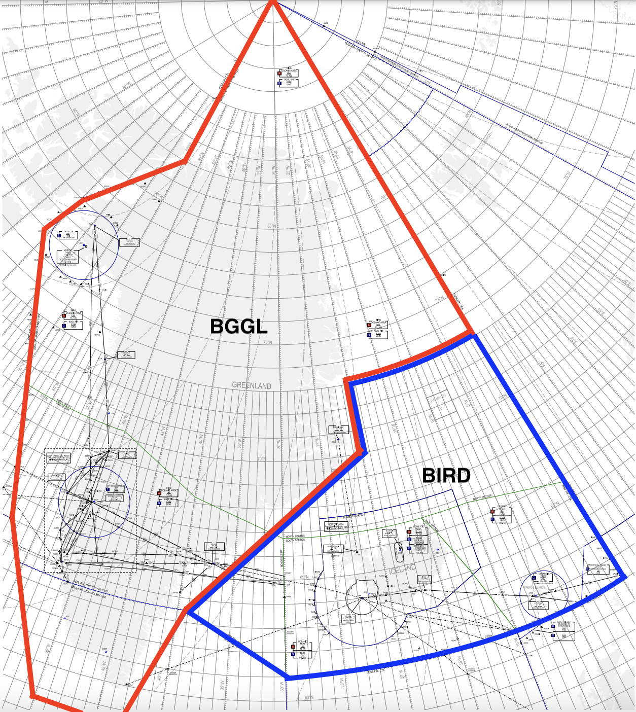
At present, Greenland delegates its enroute air traffic services to Iceland (as well as Canada.) Hence, the Reykjavik CTA consists not just of BIRD FIR, but also of the central and northern parts of BGGL FIR above FL195.
The CTA is divided into four sectors – North, South, East, and West. These sectors do not follow the FIR boundaries of BIRD or BGGL FIR.

The South sector overlies Iceland. The North sector overlies northern Greenland. The East sector overlies the Faroe Islands, and the West sector overlies central Greenland.
BGGL FIR is only delegated to the Reykjavik CTA above FL195. Below FL195, Nuuk Information provides flight information service in BGGL FIR.
Airspace Classification
Out of the seven airspace categories defined by ICAO, the Reykjavik CTA uses five: A, C, D, E, and G.
| Class | Separation Provided | Service Provided | Speed Limit | Radio Communication Requirement | Subject to ATC Clearance |
|---|---|---|---|---|---|
| A |
IFR from IFR |
IFR: Air traffic control service – VFR: NOT PERMITTED |
N/A | Continuous two-way | Yes |
| C |
IFR from IFR & VFR – VFR from IFR |
IFR: Air traffic control service – VFR: Traffic information, and traffic avoidance advice upon request |
250KT IAS below FL100 | Continuous two-way | Yes |
| D |
IFR from IFR – VFR: N/A |
IFR: Air traffic control service including traffic information about VFR flights (and traffic avoidance advice on request) – |
250KT IAS below FL100 | Continuous two-way | Yes |
| E |
IFR from IFR – VFR: N/A |
Air traffic control service and traffic information about VFR flights as far as practical – Traffic information as far as practical |
250KT IAS below FL100 |
IFR: Continuous two-way – VFR: No |
IFR: Yes – VFR: No |
| G | N/A | Uncontrolled; flight information service | 250KT IAS below FL100 |
IFR: Continuous two-way – VFR: No |
No |
Classes B and F are not used in the Reykjavik CTA.
Most TMAs in the Reykjavik CTA are Class D (the Faxi TMA also has some Class A and C airspace.) All CTRs are Class D. FIZs and ATZs are Class G, but are also radio mandatory zones, meaning pilots must be in contact with the local AFIS unit.
Outside of TMAs, CTRs, and ATZ/FIZs, the Reykjavik CTA is:
- Class A above FL195.
- Class A above FL55 within the Reykjavik Oceanic Area (OCA).
- Class E within the lower portion of the Icelandic Domestic Area (3000ft – FL195.) (Note: the upper portion of the Domestic Area, from FL195-FL245, is Class A, as detailed above.)
- Class G below FL55 in the OCA, below 3000ft in the Icelandic Domestic Area, and below FL195 in Nuuk (BGGL) FIR.
Transponder Equipment
All IFR flights in the Reykjavik CTA must have a pressure-altitude reporting SSR (i.e., Mode A+C) transponder.
All aircraft within the Faxi TMA must have an SSR (i.e., Mode A) transponder.
Aircraft operating on transponder codes assigned by Reykjavik Control must keep those codes set throughout the Reykjavik OCA unless otherwise advised by ATC.
(Iceland Only) Abbreviating Local Registrations in R/T
When controlling Icelandic (BIxx) positions, in radio communications, controllers shall abbreviate local (Icelandic, with the TF- prefix) registrations as follows:
- On first contact, ATC shall always omit the TF prefix.
- E.g., the registration TF-ICE should always be spoken as “India Charlie Echo.”
- For further communications, ATC may choose to further abbreviate the callsign to its last two letters only.
- E.g., TF-ISN, normally spoken as “India Sierra November,” may be abbreviated further to “Sierra November."
This is different from the standard ICAO convention for callsign abbreviation, which is detailed below.
For foreign (non-Icelandic) registrations, controllers shall use the standard ICAO convention for abbreviating registrations in radio communications. I.e.,
- On first contact, ATC must always use the full registration.
- E.g., G-ABCD must be read out as “Golf Alpha Bravo Charlie Delta.”
- For further communications, ATC may abbreviate the callsign to its first letter + last two letters.
- E.g., G-ABCD may be abbreviated to “Golf Charlie Delta.”
The above is not applicable to Greenlandic and Faroese positions. When controlling such positions, controllers shall continue to use the standard ICAO convention for callsign abbreviation for all registrations, local and foreign.
Delivery
When performing clearance delivery, DEL must always check the following elements of an aircraft's flight plan:
- SID/departure instructions
- Flight plan route
- Initial climb (Cleared Flight Level / CFL)
- Cruising level (Requested Flight Level / RFL)
- Squawk code
As of 20th March 2024, all departing aircraft shall receive a standard IFR clearance; no oceanic clearances are to be issued.
SID/Departure Instructions
The vast majority of aircraft will depart a controlled aerodrome on a SID (Standard Instrument Departure), a published procedure starting from the aerodrome (generally specific to a runway) leading to the first enroute waypoint of the aircraft.
DEL should verify that Euroscope has assigned the flight a valid SID — i.e., valid for the active departure runway, connects to the aircraft’s flight plan route, and is appropriate for the aircraft’s performance characteristics.
If Euroscope has assigned an invalid SID, then DEL should manually assign a valid SID on the Departure List.
Non-Standard Departures
Occasionally, an aircraft may be unable to accept an assigned SID. Reasons may include having an out-of-date AIRAC, lack of navigation equipment (e.g., non-RNAV), performance constraints (unable to meet minimum altitudes or climb gradients), etc.
In this case, DEL should coordinate with the overlying Approach (APP) unit. APP will issue non-standard departure instructions which DEL shall then relay to the aircraft, such as:
- A radar vectored departure (fly heading XXX, or climb straight ahead to XXX ft.)
- Direct to the first flight plan waypoint.
- Visual climb (aircraft climb visually to their first flight plan waypoint; a left or a right turn may be specified on departure.)
Flight Planned Route
Iceland & the Faroe Islands
BIRD FIR is Free Route Airspace (FRA), meaning that aircraft departing Iceland (as well as the Faroe Islands, which underlies BIRD FIR) are generally free to determine their own routings.
However, aircraft may still be subject to certain rules and restrictions to their routing. For example, departures from BIKF and BIRK are not permitted to use the G3 airway, except if they have short-range navigational equipment only. These restrictions are described in LOPs where relevant, and may be found in the Iceland AIP, ENR 1.8.3.1.3.7.
Greenland
BGGL FIR is not Free Route Airspace.
A "domestic" airways system has been established in BGGL FIR from FL285 and below. Details on the airways may be found in the Greenland AIP, ENR 3 (ATS Routes.) Generally, flights below FL285 are expected to fly via these airways. For flights above FL285, the rules of BIRD FIR apply.
Initial Climb (CFL)
The standard initial climb from all Icelandic airports is FL290, or the aircraft's requested flight level (RFL) if lower.
Initial climb for departures from EKVG and Greenland (BG**) is at the discretion of Reykjavik Control. Traffic permitting, Reykjavik may clear the aircraft to climb directly to RFL.
DEL should verify that the initial climb is set correctly on Euroscope on the CFL (Cleared Flight Level) list item.
Cruising Flight Level (RFL)
DEL should verify that the aircraft’s Requested Flight Level (RFL), i.e. its cruising level, is valid.
In the Reykjavik CTA, IFR cruising levels are allocated following these rules:
- 2000ft – FL410: Levels are separated by 1000ft, and allocated following the East/West semi-circular rule.
- I.e., flights with an Eastbound track (000-179°) fly at odd thousands of feet, and flights with a Westbound track (180-359°) fly at even thousands of feet.
- Technically, between FL290-FL410, this is subject to RVSM approval. However, on VATSIM, we assume that any aircraft requesting to fly in RVSM airspace is RVSM approved.
- Above FL410: Levels are separated by 2000ft. E.g., FL410 Eastbound, FL430 Westbound, FL450 Eastbound, etc.
Squawk Code
After DEL has checked all of the above elements of the flight plan, DEL should assign the aircraft a discrete four-digit squawk code (aka SSR, or secondary surveillance radar, code) via TopSky.
Clearance Format/Phraseology
[CALLSIGN], cleared to [DEST] via [SID], climb via SID [CFL], [SQUAWK].
E.g.,
🎧 ICE123, cleared to London Heathrow, via the LUTER 2A departure, climb via SID FL290, squawk 4110.
Reroutes
It is generally assumed that unless stated otherwise, an aircraft is being cleared via its flight planned route. If there are any amendments to the routing, DEL shall state them after the SID. E.g.,
🎧 FLI401, cleared to Vagar with a reroute, via the OSKUM 3A departure, after OSKUM direct MY, climb via SID FL290...
It is good practice to indicate that there will be a reroute using language such as "with a reroute" when issuing the clearance, to ensure the pilot is ready to copy.
For partial reroutings, DEL may use the phrase "flight planned route" to indicate where the original route would resume. E.g.,
🎧 ICE123, cleared to London Heathrow with a reroute, via the OSKUM 3A departure, after OSKUM direct RATSU then flight planned route, climb via SID FL290...
If the rerouting is very long, DEL may provide the new routing via a separate transmission, before issuing the clearance itself, to reduce the length of each transmission. If the reroute was provided separately before the clearance, the clearance itself does not need to specify "with a reroute."
Non-Standard Departure Instructions
For aircraft which are not following a SID, then their departure instructions (as coordinated with APP) should be given following the phrase “after departure runway XX…” E.g.,
🎧 ICE236, cleared to Akureyri, after departure runway 01 fly heading 040, initial climb 5000ft, squawk 1217.
Since the aircraft is not following a SID, the initial climb may be issued simply as “initial climb" (or simply "climb" if the aircraft will climb all the way to cruise.)
Whenever an aircraft is maintaining the runway heading/track after departure, the instruction "climb straight ahead to [LEVEL]" may be used to serve as both the departure instruction & the initial climb.
After Issuing Clearance
Upon the pilot's correct readback, they should be instructed to report ready for push & start on the delivery frequency. Only when the aircraft is ready should they be transferred to GND. This is to ensure they are on frequency, should DEL have to re-clear them.
If a VFR departure calls DEL, DEL shall instruct them to contact GND. DEL does not issue VFR clearances.
Ground
Pushback & Startup
In the Reykjavik CTA, all aircraft require clearance for startup, except for single-engine fixed-wing aircraft, and aircraft at uncontrolled aprons (as described in LOPs, e.g., Fluggardar at BIRK.) Single-engine fixed-wing aircraft may start up without ATC approval.
- Startup clearance may generally be issued upon request, except (for IFR departures) if flow control measures are in force. See the Flow Control page for more information.
If an aircraft requires pushback as well from its stand, GND may issue the pushback & startup clearance together (i.e., “push and start clearance.”).
Aircraft must have their squawk code set and their transponder on before they may be cleared for pushback.
First Contact with VFR
Upon first contact with VFR aircraft, GND should assign them a discrete (i.e., unique) squawk code, provide them with the local QNH, and ask for their intentions.
Some registrations and callsigns have allocated squawk codes in Iceland (i.e., those registrations/callsigns will always use that squawk code.) These are published in an AIC in the Iceland AIP, currently AIC A 09/2023 (published Aug 2023.)
The BIRD sector file is configured to assign these codes automatically, so ATC does not generally need to handle these aircraft differently than others.
GND should coordinate with TWR to inform them of the aircraft’s intentions. This must be done before the aircraft reaches the runway holding point, so that TWR may advise if the pilot’s intentions cannot be accommodated due to airspace congestion in the CTR.
Taxi
Before taxiing, aircraft must be squawking their assigned code & their transponder must be on.
Taxi instructions should include the aircraft's taxi route and destination, as well as any necessary information or instructions to avoid obstacles or conflicting traffic (e.g., hold short, conditional instructions, etc.)
ICE123, taxi via N and E to holding point runway 01, cross runway 28, give way to the British Airways A320 on N.
If an aircraft will taxi through an apron as a part of its taxi, one may choose to include the apron in the taxi clearance, along with the cardinal direction that the pilot will be following. E.g., taxi southbound on the East Apron." This is not strictly necessary, but can improve the clarity of the taxi instructions.
Runway Crossing & Backtracking
TWR must approve all runway crossings, and GND communicates the crossing clearances to aircraft. I.e., aircraft remain on GND’s frequency during the crossing, even though the approval to cross comes from the TWR controller.
For inactive runways, TWR may issue a “blanket clearance” to GND to allow runway crossings on that runway without coordinating each individual aircraft with TWR. Any blanket clearance becomes automatically invalid if the runway in question becomes active, even if only for a one-off departure or arrival.
For active runways, GND shall always coordinate an individual clearance for each aircraft that must cross that runway. No blanket clearances may be granted.
If any aircraft must taxi on a runway for any reason, GND shall coordinate with TWR first, then transfer the aircraft to TWR when holding short of the runway.
Reaching the Holding Point
Once a departing aircraft is approaching the runway holding point for departure (or for taxiing/backtracking on a runway), GND should transfer the aircraft to TWR.
Tower
Determining the Active Runway
Controllers should determine the active runway based on the following factors:
- Winds – Choosing the runway with the largest headwind component.
- Runway length/characteristics – If the headwind component between two runways is similar, choosing the one which is longer, or which has an ILS, etc.
- Local procedures (e.g., preferred runway for noise abatement, if one exists.)
Flexibility should also be granted where possible. Traffic permitting, one should make all reasonable efforts to accommodate any requests from pilots to use non-active runways.
Control Zone (CTR)
In addition to the runways, TWR is also responsible for the Control Zone (CTR), the airspace immediately surrounding their airport. This includes controlling VFR arrivals, departures, and aircraft in the circuit. See the VFR Guide for more information.
Takeoff Clearances
Takeoff clearances must not be issued unless all departing traffic ahead has crossed the end of the runway or begun a turn, and any arriving traffic ahead is clear of the runway. The only exception is if reduced runway separation minima (RRSM) is being applied; see below.
The takeoff clearance should include:
- Winds
- Departure runway
- (Intersection departures only) The runway intersection
- (IFR departures only) The next ATS unit which the aircraft will be contacting.
- This may be omitted if one is covering TWR top-down.
For example:
🎧 FNA102, when airborne contact Keflavik Approach on 119.300, winds 170 degrees 12 knots, runway 19 from S, cleared for takeoff.
For VFR departures, the takeoff clearance should include the flight’s VFR clearance to join the circuit, VFR route, or leave the control zone. See the VFR Guide for examples.
Taxiing on the Runway
Any taxiing or backtracking on the runway shall be conducted on the TWR frequency. TWR shall transfer the aircraft back to GND once it is clear of the runway.
Departure Separation
Fixed-wing aircraft departing on the same route must have at least 5 NM constant or increasing separation in trail. TWR and APP shall be jointly responsible for ensuring this.
Wake turbulence separation must be applied between departures when the second (trailing) aircraft is a lighter WTC than the first (preceding) aircraft, and they are using:
- The same runway
- Parallel runways separated by less than 760m (2500ft)
- Intersecting runways, if the projected flight path of the second aircraft will cross the projected flight path of the first aircraft at the same altitude or less than 300m (1000ft) below
- Parallel runways separated by 760m (2500ft) or more, if the projected flight path of the second aircraft will cross the projected flight path of the first aircraft at the same altitude or less than 300m (1000ft) below.
At the time of writing, no airport under the Reykjavik CTA currently has parallel runways.
A minimum time separation shall be applied as follows:
|
MINIMUM TIME-BASED SEPARATION FOR DEPARTURES |
|||||
|
|
First (Preceding) Aircraft |
||||
|
Light (L) |
Medium (M) |
Heavy (H) |
Super (J) |
||
|
Second (Trailing) Aircraft |
Light (L) |
— |
2 min |
2 min |
3 min |
|
Medium (M) |
— |
— |
2 min |
3 min |
|
|
Heavy (H) |
— |
— |
— |
2 min |
|
|
Super (J) |
— |
— |
— |
— |
|
One should further add 1 minute to the wake turbulence separation time after any departures from an intermediate point. Touch-and-goes are considered to be departures from an intermediate point. E.g.,
- A Light departure behind a Heavy departure from an intersection requires 3 mins of separation.
- A Medium aircraft behind a Super aircraft doing a touch-and-go requires 4 mins of separation.
To maximize efficient use of the runway, if two departures require either wake turbulence or route separation, TWR should utilize the delay time between the two aircraft to allow other aircraft not requiring separation to depart.
Landing Clearances
Landing clearances must not be issued unless all departing traffic ahead has crossed the end of the runway or begun a turn, and any arriving traffic ahead is clear of the runway. The only exception is if reduced runway separation minima (RRSM) is being applied; see below.
A landing clearance shall contain the current winds, the arrival runway, and the phrase “cleared to land.” For example:
🎧 ICE403, winds 190 degrees 6 knots, runway 19, cleared to land.
If one previously gave an aircraft the winds & landing runway in a “continue approach” instruction, and neither have changed since then, one does not need to say them again in the landing clearance.
If TWR anticipates that the aircraft will be cleared to land less than 4 NM from the airport, TWR should tell the aircraft to “expect late landing clearance.”
Reduced Runway Separation Minima
Some aerodromes in Iceland allow the use of reduced runway separation minima (RRSM) in some limited circumstances.
As of the time of writing, these procedures apply only to the following aerodromes: BIKF, BIRK, BIAR.
Aircraft Categories
For purposes of applying RRSM, aircraft are divided into three categories:
- Category 1: Single-engine propeller aircraft with a maximum certificated take-off mass of 2000kg or less.
- E.g., Cessna 172 (C172), Diamond DA-40 (DA40), etc.
- Category 2: Single-engine propeller aircraft with a maximum certificated take-off mass of more than 2000kg but less than 7000kg; and twin-engine propeller aircraft with a maximum certificated take-off mass of less than 7000kg
- E.g., Cessna Caravan (C208), Diamond DA-42 (DA42), etc.
- Category 3: All other aircraft.
To find an aircraft's maximum certificated takeoff weight, as well as other useful performance characteristics, one may visit the Eurocontrol Aircraft Performance Database at contentzone.eurocontrol.int/aircraftperformance/default.aspx.
Conditions for RRSM
Reduced runway separation minima is subject to the following conditions:
- Must be within the hours of daylight (30 mins after local sunrise to 30 mins before local sunset.)
- Shall not apply between a departing aircraft and a preceding landing aircraft.
- Wake turbulence separation minima shall be applied.
- Visibility shall be at least 5km and ceiling shall not be lower than 300m (1000ft.)
- Tailwind component shall not exceed 5 KTS.
- There shall be available means to assist the controller in assessing the distances between aircraft.
- For VATSIM purposes, it is acceptable to use the Euroscope-provided ground radar for this purpose.
- Minimum separation continues to exist between two departing aircraft immediately after take-off of the second aircraft.
- Traffic information shall be provided to the flight crew of the succeeding aircraft concerned.
- The Runway Condition Code shall not be lower than 5 on any part of the runway.
Separation to Be Applied
For VATSIM purposes, controllers may use the Euroscope "click and drag" vector tool to measure out the distances required below.
As the Euroscope vector tool shows distances in nautical miles (NM), below are some helpful rough conversions of the distances listed below into NM:
• 600m ≈ 0.5 NM
• 1500m ≈ 1 NM
• 2400m ≈ 1.5 NM
(The above conversions have been rounded up to the nearest .5, for safety and ease of memorization.)
Landing Aircraft
A succeeding landing Category 1 aircraft may cross the runway threshold when the preceding aircraft is a Category 1 or 2 aircraft which either:
- Has landed and has passed a point at least 600m from the threshold of the runway, is in motion and will vacate the runway without backtracking; or
- Is airborne and has passed a point at least 600m from the threshold of the runway.
A succeeding landing Category 2 aircraft may cross the runway threshold when the preceding aircraft is a Category 1 or 2 aircraft which either:
- Has landed and has passed a point at least 1500m from the threshold of the runway, is in motion and will vacate the runway without backtracking; or
- Is airborne and has passed a point at least 1500m from the threshold of the runway.
A succeeding landing aircraft may cross the runway threshold when a preceding Category 3 aircraft:
- Has landed and has passed a point at least 2400m from the threshold of the runway, is in motion and will vacate the runway without backtracking; or
- Is airborne and has passed a point at least 2400m from the threshold of the runway.
Departing Aircraft
- A Category 1 aircraft may be cleared for take-off when the preceding departing aircraft is a Category 1 or 2 aircraft which is airborne and has passed a point at least 600m from the position of the succeeding aircraft
- A Category 2 aircraft may be cleared for take-off when the preceding departing aircraft is a Category 1 or 2 aircraft which is airborne and has passed a point at least 1500m from the position of the succeeding aircraft; and
- An aircraft may be cleared for take-off when a preceding departing Category 3 aircraft is airborne and has passed a point at least 2400m from the position of the succeeding aircraft.
Consideration should be given to increased separation between high performance single-engine aircraft and preceding Category 1 or 2 aircraft.
Go-Arounds & Missed Approaches
Go-arounds may be initiated by the pilot or ATC, if either one feels that the approach cannot be safely continued. TWR must instruct aircraft to go around if they will cross the runway threshold before the aircraft ahead is airborne or clear of the runway (the only exception is if RRSM is being applied, in which case see above.)
IFR go-arounds should generally be instructed to follow the standard missed approach. If an aircraft is flying a visual approach, or is unable to follow the standard missed approach, then they should be given instructions such as a heading or visual climb, as defined by LOPs.
VFR go-arounds may simply be instructed to (re)join the circuit. This may include making an early turn onto downwind, if necessary to avoid conflicts.
TWR must coordinate all IFR go-arounds with Approach (APP) before transferring the aircraft back to APP! APP may tell TWR to relay de-conflicting instructions to the go-around aircraft, such as a heading or climb/stop climb, in order to avoid conflicts with airborne aircraft.
Maintaining the ATIS
At aerodromes with an ATIS, it is TWR’s responsibility to maintain the ATIS. If TWR is offline, then APP or area control units who are covering TWR top-down shall maintain the ATIS. Only if there are no overlying APP/area control units online should GND or DEL maintain the ATIS.
Aerodrome Flight Information Service (AFIS)
Introduction to AFIS
Aerodrome Flight Information Service (AFIS) is the provision of flight information service to aircraft in the vicinity of an aerodrome. This includes traffic information, weather information, aerodrome conditions, hazards & obstructions, and any other information which may be relevant to the safe navigation of a flight.
Generally, an AFIS unit will have either the callsign "Information" (in Iceland) or "AFIS" (in Greenland and EKVG.)
There are two regulatory environments in which AFIS is provided beneath the Reykjavik CTA: Iceland, which is managed by Iceland's ANSP Isavia, and Greenland/Faroe Islands (abbreviated "GLFI" in this guide), which are managed by Denmark's ANSP Naviair.
These two regulatory environments are similar, but have occasional differences. Where relevant, the procedures below will distinguish between Iceland and GLFI operating procedures.
There are a lot of regulatory differences in the provision of AFIS across the various countries that provide it around the world. E.g., in some countries, AFIS does not direct any ground traffic or set an active runway, whereas they do in Iceland & GLFI (see below).
The information in this guide is therefore not a universal guide to AFIS, but how it is uniquely provisioned in Iceland & GLFI.
Area of Responsibility
Most AFIS aerodromes have an associated FIZ (Flight Information Zone – the term used in GLFI) or ATZ (Aerodrome Traffic Zone – the term used in Iceland.) Aircraft must be in two-way radio communication with the AFIS unit within the FIZ or ATZ.
Some Icelandic AFIS aerodromes do not have an ATZ. In such cases, aircraft must be in two-way radio communication with the AFIS unit when in the “vicinity of the aerodrome.” This is defined as being within, entering, or leaving the traffic circuit.
Differences from Controlled Aerodromes (Summary)
NOTE: The following procedures have recently been revised, to reflect that AFIS units in both Iceland and Greenland have ground movement authority outside of runways.
AFIS is not air traffic control. AFIS units may not issue clearances or other instructions to airborne aircraft, or aircraft on runways. AFIS units may, however, provide some limited instructions to aircraft on the ground.
The table below briefly summarizes the key differences between controlled aerodromes and AFIS. For those unfamiliar with AFIS, keep reading — these differences will be discussed in more detail.
|
Controlled Aerodromes |
AFIS |
|
“Cleared to…” |
“Reykjavik Control clears you to…”
Clearance is not issued by AFIS but by an overlying ACC unit. |
|
"Information [letter] is current/correct..." |
The same, at the few AFIS aerodromes with an ATIS (e.g., BGGH.)
Most AFIS aerodromes do not have an ATIS. In those cases, pilots should be offered the latest weather upon readback of their clearance, or first contact for VFR. |
|
“Runway in use…" |
The same; AFIS sets active runways. |
|
“Startup approved” / “Push and start approved” |
The same. Pilots must contact AFIS before startup, and AFIS may direct ground movements outside of runways. |
|
“Taxi to… via…” |
Partially the same; AFIS may direct ground movements outside of runways. AFIS may also refuse aircraft permission to enter runways (e.g., “hold short" or "remain clear of runway XX.”) |
|
“Cleared for takeoff” |
“No reported traffic runway [XX]”
AFIS does not issue takeoff/landing clearances. AFIS only reports on the status of the runway and relevant traffic. |
|
“Cleared to land” |
|
|
“Line up and wait” |
“Runway [XX] is occupied, traffic is…”
See above. |
|
“Hold short runway [XX]” / “Hold position” |
|
|
“After departure leave the control zone…” (VFR departure instructions) |
No equivalent. AFIS does not issue VFR clearances/instructions for airborne aircraft. |
IFR Clearances
IFR aircraft request clearance via the local AFIS unit, following the steps below.
- The IFR aircraft requests clearance to the local AFIS unit, who shall then relay the clearance request to Reykjavik ACC.
- This can be done via any means of verbal coordination (e.g., Discord VC, VATSIM PMs, etc.)
- For Iceland & the Faroe Islands: The lowest sector of Reykjavik Control overlying the aerodrome shall issue the clearance.
- For Greenland:
- Iceland Radio is first preference to issue the clearance.
- If Iceland Radio is offline, and the airport underlies the West sector, then the lowest West sector controller of Reykjavik Control shall issue the clearance.
- If the airport does not underlie the West sector, and Iceland Radio is offline, then no clearance shall be issued and the aircraft shall be instructed to depart at its discretion.
- Reykjavik ACC shall issue the clearance to the AFIS unit.
- Clearances may be issued via a SID if available, in which case the aircraft must enter controlled airspace following the SID.
- Alternatively, the clearance may issued without departure instructions – i.e., "cleared to [DEST] via flight planned route." In which case the aircraft may manuever at its own discretion on departure, and shall enter controlled airspace tracking towards the first waypoint of its flight plan.
- The AFIS unit relays the clearance to the pilot, and verifies the pilot's readback.
- When relaying the clearance, AFIS units shall relay the clearance exactly as provided by Reykjavik ACC, except that they shall use the phrase "Reykjavik Control clears you to..." instead of "Cleared to..."
- This indicates that the clearance was issued under the authority of Reykjavik ACC, not the AFIS unit.
- This is true even if Iceland Radio issued the clearance, because Iceland Radio is part of Reykjavik ACC.
- When relaying the clearance, AFIS units shall relay the clearance exactly as provided by Reykjavik ACC, except that they shall use the phrase "Reykjavik Control clears you to..." instead of "Cleared to..."
If there is no overlying ATC, or if the aircraft will not enter controlled airspace at all during its flight (e.g., domestic Greenland traffic remaining below FL195 the entire flight), then the aircraft shall be told to depart at its discretion.
There is no AFIS equivalent to VFR departure, arrival, or circuit clearances. VFR aircraft simply depart and arrive at their discretion.
Weather Information
AFIS aerodromes do not typically have an ATIS broadcast. Therefore, AFIS shall offer all aircraft the latest weather (met) information – for departures, after readback of their clearance, and for arrivals, on first contact. This shall always include the winds and QNH, and may also include other significant meteorological information (SIGMET, turbulence, etc.) The full met report shall be provided upon request.
(Note: Pilots may have also have obtained the METAR from their own sources. If a pilot does not require the weather, the AFIS unit does not need to provide the full met report, but must still provide the latest QNH.)
At some aerodromes, AFIS uses a Turbulence Weather Indicator (TWI) to predict expected turbulence on departure/arrival based on local winds.
For EKVG, one of our controllers, Ollie Killean, has created a simulated TWI webpage using data pulled from the Faroese AIP, available here: https://vats.im/twi
Suggested phraseology is "[Light/moderate/severe] turbulence indicated for [departure/arrival] runway [XX]."
Thanks to Ollie for creating this!
Runway in Use
AFIS units determine an active runway for their airport. See the Tower SOP for how to select an active runway.
AFIS units shall notify the overlying Reykjavik ACC controller, as well as Nuuk Information (BGGL_FSS) for Greenlandic airports, of their chosen active runway.
At EKVG: If turbulence is indicated as severe for any runway by the TWI, then EKVG AFIS shall close that runway for departures and/or arrivals (whichever has severe turbulence indicated.) EKVG AFIS shall also notify the overlying Reykjavik ACC controller accordingly.
Suggested phraseology is: "Runway [XX] closed for [departure/arrival], severe turbulence indicated."
Ground Movements
In Iceland and GLFI, AFIS units are generally authorized by airport management to direct ground movements outside of runways, and have the authority to refuse the entry of aircraft onto runways.
This means that aircraft will call AFIS for startup, pushback, and taxi. AFIS shall provide startup clearance. For ground pushback & taxi, aircraft may navigate at their discretion, but if AFIS sees any conflicting traffic, AFIS may instruct aircraft to hold position, take an alternative route, etc.
Note that while AFIS can instruct an aircraft to hold short of/remain clear of the runway, AFIS lacks any authority over what the aircraft does once it is on the runway (crossing, backtracking, lining up, etc.)
Takeoff & Landing
AFIS units shall not issue takeoff or landing clearances. If the runway is clear of traffic, then the AFIS unit shall inform departing or arriving aircraft that there is “no reported traffic runway XX.” (simply "no reported traffic on the runway" is acceptable at a single runway airport.)
Aircraft, when told this, may line up, depart, or land on the runway at their own discretion.
For example:
🎧 FLI402, winds 130 degrees 4 knots, no reported traffic runway 12.
If there is traffic blocking the runway in any way, then the AFIS unit shall inform departing aircraft “runway XX occupied,” provide traffic information, and ask for the aircraft’s intentions. For example:
🎧 FLI402, runway is occupied, traffic is a company A320 backtracking to vacate the runway, report intentions.
NOTE: Even if the runway is occupied, aircraft may still use that runway at their discretion. They are only obligated by the rules of the air not to hinder other traffic.
E.g., if one aircraft is vacating at one end of the runway, another aircraft may reasonably line up on the opposite end of the runway, if doing so would not obstruct the vacating aircraft.
Traffic/Flow Management Strategies
Generally speaking, the inability of AFIS to control when aircraft choose to depart poses a significant limitation on AFIS's ability to control the flow of inbound/outbound traffic. This may be remedied using two strategies.
- Firstly, AFIS may provide traffic management suggestions to pilot.
- E.g., "traffic are two aircraft, one on initial approach and one on short final, suggest you remain in the hold for spacing," or "traffic is a Boeing 757 departed 1 minute ago, suggest you delay departure by 2 minutes for wake turbulence and route separation"
- Secondly, AFIS may coordinate with the overlying ACC unit to issue "valid at" clearances (e.g., "clearance valid at time 1234z").
- While this is not strictly speaking a prohibition on an aircraft's ability to take off, a clearance not being valid means the aircraft would not be able to proceed on its planned flight, so it is practically speaking required to wait until its clearance is valid before commencing its departure roll.
Airborne Traffic
AFIS units shall proactively offer traffic, weather, and aerodrome information to aircraft in their area of responsibility, in order to facilitate their safe navigation.
Traffic information should be provided using procedural methods, since AFIS units generally do not have radar. Thus, AFIS units may ask aircraft to provide position reports, such as:
- Waypoints/fixes on their route, or on published SIDs, STARs, and approach procedures which the aircraft intends to fly
- Positions relative to the airport or a waypoint/fix (e.g., abeam the airport, 5 NM from XX NDB, etc.)
- Phases of approach (e.g., final, established on the ILS, etc.)
- Legs of the traffic circuit (e.g., downwind, final, etc.)
Aircraft arriving an aerodrome (entering the ATZ/FIZ or traffic circuit) shall be told the active runway as well as any relevant traffic information.
At certain aerodromes (e.g., BGGH), there may be mandatory reporting points for aircraft. Refer to the SOP for those airports for clarification.
Aircraft do not require the AFIS unit's approval to leave the frequency once they are outside of the ATZ/FIZ/vicinity of the aerodrome. However, if the aircraft will be entering controlled airspace, AFIS should advise them to contact the relevant ATC unit.
- E.g., at EKVG, aircraft should be advised to contact Reykjavik Control approaching 7500ft.
ATS Surveillance (APP & Area Control)
This page details procedures for providing air traffic control service using ATS surveillance (secondary radar, MLAT, or ADS-B.) This includes Approach (APP) and Area Control positions.
Transition Altitude & Level
The Transition Altitudes in the Reykjavik CTA are:
- Iceland: 7000ft
- Faroe Islands (EKVG): 7500ft
- Greenland: Varies by aerodrome, see table below for reference.
|
Airport |
TA |
|
Ilulissat (BGJN) |
6000ft |
|
Kulusuk (BGKK) |
7000ft |
|
Maniitsoq (BGMQ) |
9000ft |
|
Narsarsuaq (BGBW) |
9000ft |
|
Constable Pynt (BGCO) |
6000ft |
|
Nuuk (BGGH) |
7000ft |
|
Paamiut (BGPT) |
6000ft |
|
Qaanaaq (BGQQ) |
6500ft |
|
Sisimiut (BGSS) |
8000ft |
|
Upernavik (BGUK) |
6000ft |
|
Uummannaq Qaarsut (BGUQ) |
10,000ft |
|
Aasiaat (BGAA) |
6000ft |
NOTE: The TAs listed above may become out of date over time. Please always refer to the AIP for the correct TA of a given airport or region.
The Transition Level shall be determined by adding a certain number of feet to the Transition Altitude, depending on the current local QNH. The following table shall be used:
|
QNH |
<929 |
930-946 |
947-963 |
964-979 |
980-996 |
997-1012 |
>1013 |
|
TL |
+3000ft from TA |
+2500ft |
+2000ft |
+1500ft |
+1000ft |
+500ft |
+0ft |
Horizontal Separation Under ATS Surveillance
In practice, the minimum horizontal separation under ATS surveillance in the Reykjavik CTA/OCA is:
- 3 NM within 30 NM radius of KFV VOR (to be used only by Keflavik & Reykjavik Approach)
- 5 NM east of 30W*
- 10 NM west of 30W*
*Strictly speaking, per Icelandic regulations, this is subject to the use of ADS-B surveillance and the altitude/level of the aircraft. Because enroute ADS-B surveillance is now available throughout the entire Reykjavik CTA/OCA, in practice the distinction between 5 & 10 NM separation is the 30W meridian (the boundary between the West & South sector) with level not being a factor.
Vertical Separation
The minimum vertical separation in the Reykjavik CTA is as follows:
- Below FL290: 1000ft for all aircraft
- FL290-FL410: 1000ft* or 2000ft between a formation flight and any other aircraft
- Above FL410: 2000ft for all aircraft
- At or above FL450: 4000ft between supersonic aircraft, and between supersonic aircraft and any other aircraft
*Technically, this is subject to aircraft being RVSM-equipped. However, on VATSIM, we assume that any aircraft that has filed an RFL above FL290 is RVSM-equipped.
Wake Turbulence Separation
Following ICAO standards, the following minimum distances must be applied whenever:
- An aircraft directly follows another at the same altitude or less than 1,000 ft below it
- If both aircraft are using the same runway or parallel runways separated by less than 760m
- An aircraft is crossing behind another aircraft, at the same altitude or less than 300m (1000 ft) below
|
MINIMUM WAKE TURBULENCE SEPARATION (Nautical Miles) |
|||||
|
|
First (Preceding) Aircraft |
||||
|
Light (L) |
Medium (M) |
Heavy (H) |
Super (J) |
||
|
Second (Trailing) Aircraft |
Light (L) |
— |
5 NM |
6 NM |
8 NM |
|
Medium (M) |
— |
— |
5 NM |
7 NM |
|
|
Heavy (H) |
— |
— |
4 NM |
6 NM |
|
|
Super (J) |
— |
— |
— |
— |
|
A VFR trailing an IFR aircraft, as well as IFR aircraft on a visual approach, may reduce to separation below these minima. However, ATC must inform the pilot “caution wake turbulence” before the separation drops below these minima. Moreover, ATC may not instruct an aircraft to reduce below these minima – the pilot must do so on their own initiative.
Allocation of Cruising Levels
In BIRD CTA, cruising levels are allocated following these general rules:
IFR:
- Below FL410: Levels are separated by 1000ft, and allocated following the East/West semi-circular rule (i.e., Eastbound flights fly at odd thousands of feet, and Westbound flights fly at even thousands of feet)
- Above FL410: Levels are separated by 2000ft (thus, all valid levels are odd).
VFR:
- 3000ft – FL195: Levels are separated by 1000ft, and allocated following the East/West semi-circular rule + 500ft (i.e., Eastbound flights fly at odd thousands of ft + 500ft, and Westbound flights fly at even thousands of ft + 500ft).
No VFR levels are allocated above FL195, as all airspace in BIRD CTA above FL195 is Class A, and thus VFR is not permitted.
The following table of valid levels, based on Icelandic AIP ENR 1.7.5, may be used as reference:
|
WESTBOUND ← Track 180-359° ← |
EASTBOUND → Track 000-179° → |
||
|
IFR |
VFR |
IFR |
VFR |
|
2000ft |
2500ft |
3000ft |
3500ft |
|
4000ft |
4500ft |
5000ft |
5500ft |
|
6000ft |
6500ft |
7000ft |
7500ft (FL75) |
|
8,000ft (FL80) |
8500ft (FL85) |
9000ft (FL90) |
9500ft (FL95) |
|
10,000ft (FL100) |
10,500ft (FL105) |
11,000ft (FL110) |
11,500ft (FL115) |
|
12,000ft (FL120) |
12,500ft (FL125) |
13,000ft (FL130) |
13,500ft (FL135) |
|
14,000ft (FL140) |
14,500ft (FL145) |
15,000ft (FL150) |
15,500ft (FL155) |
|
16,000ft (FL160) |
16,500ft (FL165) |
17,000ft (FL170) |
17,500ft (FL175) |
|
18,000ft (FL180) |
18,500ft (FL185) |
19,000ft (FL190) |
19,500ft (FL195) |
|
20,000ft (FL200) |
|
21,000ft (FL210) |
|
|
22,000ft (FL220) |
|
23,000ft (FL230) |
|
|
24,000ft (FL240) |
|
25,000ft (FL250) |
|
|
28,000ft (FL280) |
|
27,000ft (FL270) |
|
|
30,000 ft (FL300) |
|
29,000ft (FL290) |
|
|
32,000ft (FL320) |
|
31,000ft (FL310) |
|
|
34,000ft (FL340) |
|
33,000ft (FL330) |
|
|
36,000ft (FL360) |
|
35,000ft (FL350) |
|
|
38,000ft (FL380) |
|
37,000ft (FL370) |
|
|
40,000ft (FL400) |
|
39,000ft (FL390) |
|
|
43,000ft (FL430) |
|
41,000ft (FL410) |
|
|
47,000ft (FL470) |
|
45,000ft (FL450) |
|
|
51,000ft (FL510) |
|
49,000ft (FL490) |
|
|
etc. |
|
etc. |
|
Minimum Vectoring Altitude
The Minimum Vectoring Altitude (MVA) is the minimum altitude at which ATC may clear aircraft to during vectoring/direct routing, except if otherwise authorized for radar approaches, departures, and missed approaches.
MVA areas may be specifically defined/established in certain airspaces (e.g., the Faxi TMA.) If there is no minimum vectoring altitude explicitly established for a given area, then the MVA is either the area minimum altitude (AMA) or minimum sector altitude (MSA).
Iceland's AMAs may be found in Iceland AIP, ENR 6.1-3. In Greenland or the Faroe Islands, all AMAs and MSAs are below controlled airspace, so they are irrelevant for MVA purposes.
Descent Below Controlled Airspace
Over Iceland
IFR aircraft may be cleared to descend below controlled airspace if a descent procedure (a STAR or instrument approach procedure) has been published for their arrival aerodrome. At such aerodromes, two options are possible:
- Aircraft may be cleared for a specific descent procedure first, then cleared to descend below controlled airspace.
- Aircraft may also be simply cleared to descend below controlled airspace, without specifying a procedure. However:
- Their cleared routing must include a waypoint/beacon where at least one of the published descent procedures at that aerodrome would originate from.
- They must report to ATC the procedure they intend to follow.
If an IFR aircraft wishes to descend below controlled airspace at an airport with no published descent procedures, then they may be descended no lower than the area minimum altitude (see Iceland AIP, ENR 6.1-3), and must cancel IFR for further descent.
If an aircraft wishes to fly a different procedure than previously cleared, the pilot must contact the ACC unit or local AFIS unit and request a reroute to the beacon/waypoint where their requested procedure begins from. Alternatively, the pilot may cancel IFR and continue VFR.
Over Greenland, the Faroe Islands, or the Atlantic Ocean
Where the minimum altitude of a region is below the Reykjavik CTA, such as over Greenland, the Faroe Islands, or the Atlantic Ocean, aircraft may receive clearance to descend below controlled airspace without canceling IFR, even if there is no published descent procedure.
Transfer of Control & Communications
The transfer of control between ATS units takes place at the airspace boundary, or at the transfer of control point if otherwise designated. The transferring unit should transfer communications with the aircraft to the receiving unit no less than 2 minutes or 30 NM (whichever is greater) before the transfer of control point.
For arriving traffic, communications should be transferred to Tower as early as practicable once the aircraft is established on final approach, and at no later than 6 NM final.
Silent Transfer of Control
Traffic on the same track, or crossing tracks, may be transferred silently (i.e., without prior verbal coordination) between two units if the longitudinal separation between them is at least:
- 10 NM constant or increasing when the receiving sector uses 5 NM or less separation minima (i.e., east of 30W)
- 15 NM constant or increasing when the receiving sector uses 10 NM separation minima (i.e., west of 30W)
LOAs with neighboring sectors may specify different requirements for transferring control to that sector.
If the separation between two aircraft does not meet the above requirements, they must be verbally coordinated with the next unit before transferring control. If speed control is being used to accomplish the required separation, aircraft should be instructed to report their speed to the next controller.
Releases
A release is an approval given for a receiving unit to climb, descend, and/or turn aircraft before the transfer of control point. Standard releases may be detailed in LOPs or LOAs with neighbouring sectors. They may also be coordinated verbally, or granted via the TopSky Release function.
Note:
- Releases for turns do not exceed 45° unless explicitly coordinated.
- The transferring unit remains responsible for separation within their own AoR, unless otherwise coordinated.
Hold Management
As of writing, the Reykjavik CTA currently has no published enroute holds. Published holds on STARs which are within a TMA shall be managed by the APP unit responsible for said TMA. E.g., the published holds on BIKF’s STARs, within the Faxi TMA, are managed by Keflavik Approach.
If the published holds in the TMA are full, then APP should coordinate with the overlying ACC unit to hold aircraft outside of the TMA. Such holds should be managed by the ACC unit.
Two aircraft in the same holding stack must be separated vertically by 1000ft, or greater if required by the minimum vertical separation rules. Controllers must not clear an aircraft to hold at a level lower than the Minimum Holding Altitude (MHA) for any published hold.
Published holds may be issued using the abbreviated phraseology: “Hold at [FIX] as published, [LEVEL].” For example:
🎧 ICE123, hold at MEBUN as published, FL160.
When issuing a non-published hold, or if a pilot requests the full details of the hold, the following information should be given at minimum:
- Holding fix
- Level
- Inbound track/course
The following may also be specified:
- Turn direction (left or right turns. If not specified, it is assumed that the holding shall use right turns.)
- Time/length of leg (in minutes or NM. If not specified, it is assumed that the holding shall use 1-minute legs.)
The following phraseology may be used: [CALLSIGN], hold at [FIX], [LEVEL], [INBOUND COURSE], [LEFT/RIGHT] turns, [LEG TIME/LENGTH]. For example:
🎧 ICE789, hold at MALAB, FL120, inbound course 097, left turns, 1 minute legs.
Change of Flight Rules
While the majority of flights are conducted under one set of flight rules (either IFR or VFR), aircraft may occasionally wish to change from one set of flight rules to another.
Note: If the change of flight rules would be unsafe for any reason (e.g., aircraft requests to switch to VFR but is not in VMC), or would increase the controller's workload beyond manageable levels, the controller may deny any request to change flight rules.
Flight Planning
If an aircraft plans in advance to switch flight rules at a specific point in its flight plan, it may do so by adding "VFR" or "IFR" to its flight plan routing at that point. E.g., if the flight plan routing states:
...KFV/N180A050 IFR DCT RK...
...that indicates the aircraft will request to change to IFR at KFV (at which point they will be at speed 180kts and 5000ft.)
In real life, a flight plan with a combination of IFR or VFR should be filed with the flight rule code "Y" (for IFR first then VFR) or "Z" (for VFR first then IFR.) VATSIM's flight plan form does not currently support these codes, so pilots will generally file their flight plans with the flight rules they intend to start the flight with.
Note that aircraft do not have to pre-plan a change of flight rules. Sometimes, requests to change flight rules are spontaneous, being driven by the constantly-evolving flight and weather situation (e.g., VFR flight finds itself in IMC and so requests IFR.)
VFR to IFR
For an aircraft to transition from VFR to IFR, the following conditions shall be fulfilled:
- The aircraft must be identified on ATS surveillance (if available), and the Mode C altitude return verified
- The aircraft should meet the IFR separation minima from other IFR aircraft (if not, ATC shall issue instructions to ensure this separation at the point that the IFR clearance becomes effective)
An IFR clearance may then be issued. As with IFR clearances issued on the ground, these clearances generally contain the following elements:
- Clearance limit
- Generally the destination airport, or more rarely, a specific waypoint/beacon/fix if the pilot only wishes to continue IFR to that point
- Routing
- Either "flight planned route," if the aircraft is following a previously flight planned IFR routing. ATC may also provide a routing or instructions, e.g., a radar vector
- Level
- If the aircraft will climb/descend to an altitude & they were not previously given the local QNH, they should be given the QNH as well
- Squawk (if not previously assigned)
E.g.,
🎧N804AB, cancel VFR, cleared to Isafjordur via direct KFV then flight planned route, climb FL100, squawk 4122.
The following is an example of a clearance issued to a limit that is not an airport (e.g., the pilot has requested only to be cleared to a specific published hold so they can descend IFR through clouds while holding, then cancel IFR once in VMC):
🎧(TF-)ISN, cancel VFR, cleared IFR direct to MALAB, hold at MALAB as published, descend 3000ft, report VMC.
If ATC is unable to ensure the required separation from other IFR traffic, or does not have the capacity to handle aditional IFR in their airspace, ATC shall deny the aircraft's request for an IFR clearance, and may in turn deny the aircraft permission/clearance to enter a given airspace). ATC should then ask for the aircraft's intentions.
IFR to VFR
For an aircraft to transition from VFR to IFR, the pilot shall report their intention to cancel IFR to ATC. If ATC is able to accept this, ATC shall respond by acknowledging the cancellation of IFR, noting the time of cancellation, and providing any further instructions for the aircraft's continued VFR flight. E.g.,
🎧(TF-)ABC, IFR cancellation received at 1345z, maintain VFR, join the right hand circuit for runway 13...
If ATC is aware of IMC weather conditions in the aircraft's vicinity, or if ATC does not have the capacity to handle additional VFR in their airspace, ATC shall deny the aircraft's request to cancel IFR and ask for their intentions.
Oceanic Area Control
The Reykjavik CTA is unique in that much of it is also designated as oceanic airspace. This page outlines the specific rules and procedures relevant to oceanic airspace.
As of 19th March 2026 aircraft entering the Reykjavik ACC no longer require an RCL as per Nat Doc 007 Chapter 6 section 6.3.24
Oceanic Airspace
Within the Reykjavik CTA, all controlled airspace outside of the Icelandic Domestic Area is considered oceanic airspace. This airspace is designated the Reykjavik Oceanic Area (OCA).
Because the Reykjavik ACC (Area Control Centre) is responsible for the Reykjavik OCA, it is also referred to as the Reykjavik OAC (Oceanic Area Control Centre.) The terms "Reykjavik ACC" and "Reykjavik OAC" are generally interchangeable for VATSIM purposes.
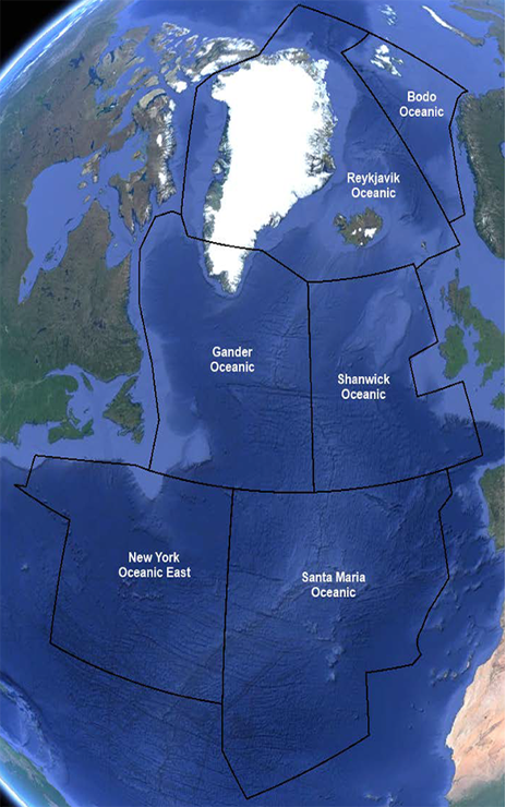
The Reykjavik OCA is one of six oceanic areas that make up the North Atlantic (NAT) oceanic airspace, together with Gander, Shanwick, New York, Santa Maria, and Bodo OFIR (Oceanic FIR).
VFR is prohibited in oceanic airspace (which is all Class A.) VFR aircraft must either fly below controlled airspace, or request IFR clearance to transit oceanic airspace.
NAT Tracks
The North Atlantic oceanic airspace uses a system of tracks called the North Atlantic Organised Track System (NAT OTS,) to regulate traffic crossing the ocean. While usually remaining in Shanwick & Gander OCAs, the tracks do occasionally enter the Reykjavik OCA.
For an introduction to the NAT OTS, read this guide published by Gander Oceanic on VATSIM. (Ignore the sections on the Tango routes & Concorde tracks, as they are not relevant to BIRD OCA.)
Entering Oceanic Airspace
When entering the Reykjavik ACC an aircraft will be identified by the controller and may request a Mach number for future planning
🧑✈️ Reykjavik Control ICE123 FL380
🎧 ICE123, Idenfied say Mach number
🧑✈️ Mach decimal 83 ICE123
🎧 ICE123, roger maintain Mach decimal 83
The controller will either then increase their mach number or decrease, depending on traffic flow within the sector, essentially if it's a group of aircraft going into Keflavik
Entering/Exiting Other NAT OCAs
Aircraft entering BIRD OCA from other NAT OCAs (e.g., Gander, Shanwick, etc.) do not have to submit another RCL message to BIRD. However, aircraft leaving BIRD OCA to another OCA will need to submit an RCL.
Within Oceanic Airspace
CPDLC
Within the Reykjavik ACC, airborne traffic can utilise CPDLC as a form of communication as per the eaip for Iceland section 3.4 Communication services
The logon code is BIRD
We do not offer PDC or DCL clearances within the Faxi TMA. This also includes the Faroe Islands and Greenland
Cost Index (ECON) Operations
In oceanic airspace, aircraft may fly in Cost Index (ECON) mode for optimal fuel efficiency – i.e., they may deviate by up to ±0.02 Mach from the Mach number originally submitted in their flight plan, without prior permission (e.g., if they submitted Mach 0.78, they may fly between Mach 0.76-Mach 0.80 without notifying ATC.)
If they deviate by >0.02 Mach from the originally reported Mach number, they must notify ATC.
Controllers may still instruct aircraft to fly a fixed Mach number if required for separation.
A similar procedure was previously known as "Operation Without Assigned Fixed Speed" (OWAFS.) The difference is that now, pilots are expected to fly ECON mode by default, not just when ATC instructs "resume normal speed."
Strategic Lateral Offset Procedures (SLOP)
Traffic in BIRD OCA above FL285 may use SLOP (Strategic Lateral Offset Procedures). This is a random offset right of the aircraft's track, intended to "artificially" induce a navigation error that reduces the likelihood two aircraft will occupy the same airspace at once.
At the pilot's discretion, aircraft with the capability to offset (using their FMS) may offset right of track (left offsets are prohibited) up to a maximum of 2 NM (the exact offset the pilot chooses should be random) ATC does not need to approve SLOP, or be informed when SLOP is in use.
Aircraft shall not apply SLOP below FL285 in the Reykjavik OCA, and shall end the use of SLOP before entering domestic airspace.
VATSIM Logon Procedures
Empty Position
Whenever logging onto a position that no one else is covering (directly or top-down), always inform adjacent and overlying controllers via the ATC chat (and also following up via private message if appropriate.)
Handing Over/Relieving a Position
Whenever logging onto a position that is being covered by someone else (directly or top-down), controllers should first:
- Ideally log on as an observer (OBS) for 5-10 minutes before connecting, to observe the traffic situation.
- Check with the other controller, to make sure they are okay with being relieved, and to agree on the time for the position handover.
- The controller taking over the position is the relieving controller and the controller who is handing over the position is the relieved controller.
Then, during the position handover:
- The relieving controller logs onto VATSIM on Euroscope and AFV using an appropriate relief callsign. Generally, one should add an extra underscore before the facility suffix (after the FIR and sector identifier) — for example,
BIKF_TWRmay be relieved byBIKF__TWR, andBIRD_S1_CTRmay be relieved byBIRD_S1__CTR.- Sometimes, AFV may not properly detect relief callsigns, especially for
_CTRpositions. In this case, one should manually add the original callsign/frequency of the position and XC on the original callsign, to allow access to the correct transceivers for the position. - If the other controller is already using a relief callsign, then one may log on with the original position callsign.
- Sometimes, AFV may not properly detect relief callsigns, especially for
- The relieved controller shall brief the relieving controller on the current situation regarding the position. This shall include, at minimum:
- TRAFFIC information for all aircraft under the position's area of responsibility, particularly those which are unusual or coordinated differently than usual.
- When controlling area control (BIRD/BGGL/BICC), for any "normal" aircraft without special circumstances to note, the relieved controller may simply transfer tags silently to the relieving controller.
- AERODROME information for all airports under the position's area of responsibility — active/preferred runways, latest ATIS letter if applicable, whether the airport is in IMC/VMC, etc.
- AIRSPACE information about any relevant active airspace area (danger, warning, etc.)
- COORDINATION agreed with neighboring sectors.
- Any other relevant INFORMATION necessary to control the position.
- TRAFFIC information for all aircraft under the position's area of responsibility, particularly those which are unusual or coordinated differently than usual.
- Once the briefing is complete, the relieving controller shall verify that:
- They have all tags assumed & all aircraft on frequency.
- They have connected all ATISes.
- They have all the information required to control their position.
Once all the above is complete, the relieved controller may disconnect, and the handover is complete.
Conduct During Position Relief
Until the handover has been formally completed, the relieving controller shall not interfere with the operation of the position. This includes:
- Not transmitting on the operational frequency unless specifically requested by the relieved controller.
- Not issuing clearances, instructions, or traffic information to aircraft.
- Not modifying tags, flight plans, scratchpads, or controller settings affecting live traffic unless coordinated.
- Not assuming control of aircraft until explicitly transferred by the relieved controller.
The relieved controller remains fully responsible for the position and all traffic under their control until the handover briefing is complete and control has been formally transferred. The relieving controller should remain in an observing and monitoring role during this period.
Mentoring
Whenever a mentor and a student are logging on, the guidelines in the VATSCA Student & Mentor SOP shall be followed. The following should be noted in particular:
- The student shall log on before the mentor. This reduces the likelihood that Euroscope will get "confused" and mistake the mentor connection as the primary controller.
- The mentor shall log on with the midfix
_M_in their callsign (e.g.,BIKF_TWR's mentor should have the mentor callsignBIKF_M_TWR.) The student may log on with the usual callsign of the position. - The mentor should verify that the student has the correct Euroscope sector ID in their controller list. E.g., BIKF_TWR should have sector ID "KFT."
- If the sector ID is displaying as simply numbers (10, 11, etc.), then the mentor may try the following steps:
-
- Log off & on again
- Use the midfix
_Z_instead of_M_ - Deselect the primary frequency of the position in Euroscope (and accept that Euroscope will not highlight the correct area of responsibility)
-
VFR Guide
A guide towards the proper handling of VFR traffic in the Reykjavik CTA (Iceland, Greenland, and the Faroe Islands.)
Basic Principles of VFR
Visual Flight Rules (VFR) governs flights operating in Visual Meteorological Conditions (VMC) – i.e., conditions in which flight solely by visual reference is possible.
Unlike IFR flights, which follow a set routing, VFR flights generally navigate at the pilot's discretion. ATC may, however, issue traffic information and avoidance advice upon request, as well as restrict VFR aircrafts' altitude, direction of flight, or entry into certain airspace, as necessary for traffic management and safety.
Restrictions and Minima
VFR flights are not permitted in Class A airspace. In the Reykjavik CTA, this is:
- All airspace above FL195.
- In the Oceanic Area (OCA), all airspace above FL55.
Secondly, VFR flights may only take place in Visual Meteorological Conditions.
- In Iceland, Greenland, and the Faroe Islands, aerodromes are considered to be in VMC if the visibility is at least 5km, and the ceiling (lowest layer of BKN/OVC clouds reported in the METAR) is at least 1500ft.
Conditions below VMC requirements are known as Instrument Meteorological Conditions (IMC). If the aerodrome is in IMC, then ATC may not give aircraft clearance to operate VFR in the control zone, except under the conditions below.
In Iceland, the only exemptions from the weather requirements for VFR are:
- Search and Rescue flights.
- Exercise flights for Search and Rescue.
- Coast Guard flights
- Ambulance and emergency flights.
If conditions are IMC, a pilot may either choose to file an IFR flight plan and receive IFR clearance, or they may request Special VFR.
There are no specific exemptions from VFR minima in Greenland and the Faroe Islands.
Special VFR
Special VFR (SVFR) is a type of VFR which a pilot may request if conditions are below VMC. The following conditions must be fulfilled for SVFR:
- ATC must give approval.
- Must be during the day.
- Must be within a CTR.
- Must be clear of cloud.
- Cloud ceiling must be at least 600ft.
ATC must ensure that SVFR flights are separated from all other airborne flights, IFR and VFR. This means:
- Only one aircraft may be in the circuit.
- There may be only one aircraft on each VFR route at once.
- Only one departure or arrival is permitted into the CTR at once.
In Greenland, the reported visibility must also not be less than 1.5km. However, when visibility is less than 1.5km, ATC may still issue clearance for flights to cross (i.e., transit) the CTR or ATZ without intending to take off, land, or join the circuit, if the flight visibility reported by the pilot is not less than 1500m, or for helicopters, not less than 800m.
Night VFR
In Iceland, VFR is permitted at night if the visibility is no less than 8km during any part of the flight. This is in addition to the usual visibility requirements for VFR flights. Additionally, all VFR flights at night must file a flight plan.
In Greenland and the Faroe Islands, there are no specific regulations regarding nighttime VFR.
Departures (Leaving the CTR)
First Contact (Ground)
On first contact with a VFR departure, Ground should assign them a squawk code, provide the local QNH (together with startup clearance, if the aircraft requires it), and ask for their intentions.
Ground should coordinate any VFR flight with TWR before the aircraft reaches the runway holding point, to notify TWR of the aircraft’s intentions. This is so that TWR may advise if they can accept the VFR aircraft’s intended operations in the CTR.
Some pertinent points to remember include:
- Single-engine aircraft, which often fly VFR, do not require startup clearance. Twin/multi-engine aircraft and helicopters require startup clearance.
- Light aircraft, which make up the majority of VFR traffic, sometimes request to perform an engine run-up. Run-up locations are noted in the aerodrome charts, or in airport LOPs. For example:
- At BIKF, there is a run-up pad abeam of taxiway K.
- At BIRK, there are two run-up areas – south of Hangar 4 (on the North Apron, next to taxiway G), and one southwest of Hangar 8 (on the East Apron).
As with IFR, VFR aircraft must have their squawk code set & transponder on (XPDR/Mode C) before taxi or pushback, whichever comes first.
VFR Departure Clearance
For departing VFR flights, VFR departure instructions shall be given together with the takeoff clearance. This includes:
- The routing of the aircraft within the control zone, i.e.,
- The VFR route (if the aircraft is following one), or:
- The cardinal direction (N/E/S/W) if the aircraft is not on a VFR route.
- Any relevant departure instructions (e.g., left or right turn after departure – not required to be specified if obvious)
- The altitude if the aircraft is not on a VFR route
- For aircraft departing via a VFR route, since the route altitudes are published, it is not required to state the route altitude unless the pilot requests it.
- For aircraft not on a VFR route, within the control zone, generally 1500FT is appropriate for single-engine light aircraft, and 2500FT is appropriate for multi-engine aircraft and turboprops.
The following phraseology shall be used for aircraft on a VFR route:
[CALLSIGN], [DEPARTURE INSTRUCTIONS* for] route [X], [WINDS], [RWY], cleared for takeoff.
(*may be omitted)
E.g.,
🎧 (TF-)SKN, right turn for route 6, winds 180 degrees 14 knots, runway 19, cleared for takeoff.
The following phraseology may be used for aircraft not on a VFR route:
[CALLSIGN], [DEPARTURE INSTRUCTIONS* to] leave the control zone to the [N/E/S/W], [ALTITUDE], [WINDS], [RWY], cleared for takeoff.
(*may be omitted)
E.g.,
🎧 (TF-)MYB, leave the control zone to the East, 2500ft, winds 300 degrees 15 knots, runway 31, cleared for takeoff.
Once the aircraft is airborne, the pilot should then be asked to report when they are approaching the boundaries of the CTR.
- For BIKF & BIRK:
- If on a VFR route, the pilot should report passing the reporting point immediately prior to the airspace boundary, e.g., Aluminium Factory for BIRK departures on route 6.
- If not on a VFR route, the pilot should report 6 NM out from BIRK, or 12 NM out from BIKF.
- Other aerodromes:
- Aircraft may simply be asked to report leaving the control zone.
Before an aircraft leaves the CTR, TWR must coordinate with any neighboring ATC whose controlled airspace the aircraft will enter. TWR shall inform the next controller of the aircraft’s callsign, altitude (current, as well as requested if different), and their intentions.
Circuits
A standard traffic circuit consists of four legs: crosswind, downwind, base, and final.

In general, a standard traffic circuit is a left-hand circuit at 1000ft AGL. (This is general common practice, and is in fact a rule in Iceland.)
Certain aerodromes, however, may have published circuits which are non-standard in some way. For example, BIKF has a standard circuit altitude of 1200ft, and uses right hand circuits for RWYs 10 & 19. Consult with LOPs and the AIP to confirm if an airport has a published non-standard traffic circuit.
VFR departure clearances for circuits shall include the direction of the circuit (left/right.) While not strictly required, it is recommended to also state the altitude of the circuit, as VATSIM pilots are often unfamiliar with standard circuit altitudes. The following phraseology shall be used:
[CALLSIGN], [LEFT/RIGHT] hand circuits, [ALT]*, [WINDS], [RWY], cleared for takeoff.
(*may be omitted)
For example:
🎧 (TF-)SKN, right-hand circuits, 1000ft, winds 020 degrees 6 knots, runway 01, cleared for takeoff.
When an aircraft is in the circuit, TWR should inform them of their order in the sequence, and confirm their intentions if not previously known (touch & go, full-stop landing, etc.)
While it is not required for aircraft to report any particular leg of the circuit if not prompted, one may ask an aircraft to report upwind, downwind, crosswind, base, or final if one considers it necessary to maintain situational awareness and manage the traffic in the CTR.
At any point once there is no further traffic ahead in the sequence, TWR may clear an aircraft in the circuit to land (or perform a touch & go, low approach, etc.
- If the aircraft is doing a full-stop landing, they will land and vacate the runway, after which TWR/GND may taxi them to the appropriate apron (e.g., Fluggardar).
- If an aircraft is doing a low approach, touch & go, or stop & go (stopping on the runway, then taking off again), then once they are climbing, TWR should give them their new order in the sequence (if it has changed), ask for their intentions again, and then repeat all of the above.
Occasionally, a VFR arrival may have to go around. If there is conflicting traffic, the aircraft should be instructed to turn left/right immediately for an early crosswind, to avoid a collision. Otherwise, they may simply rejoin the circuit as usual.
Arrivals (Entering the CTR)
If a VFR aircraft is entering the CTR controlled airspace, the transferring unit (i.e., the ATS unit currently responsible for the aircraft) will coordinate their arrival beforehand.
In heavy traffic situations, one may make requests to the transferring unit such as changing the aircraft's altitude or routing, or even refuse the aircraft's entry in the CTR, if necessary for traffic management and sequencing.
For VFR aircraft entering from uncontrolled airspace, one should send a .contactme to the pilot ideally 2-5 minutes before they will enter one’s airspace.
Upon first contact with a VFR arrival, one should confirm what the intentions of the aircraft are (e.g., full-stop landing, touch-and-go, low approach, etc.). Then, one may issue an appropriate VFR arrival clearance. One should also assign a squawk code if the aircraft has not already been assigned one.
In Iceland, clearance to enter airspace is considered given once the controller gives airport information (e.g., QNH, runway in use, etc.) and route clearance.
For arrivals inbound on a VFR route, “route clearance” means the VFR route and the arrival runway, and an instruction to report passing the last VRP of the route. The following phraseology may be used:
[CALLSIGN], route X for runway XX, [QNH], [SQUAWK if necessary], report passing [REPORTING POINT.]
🎧 (TF-) SKN, route 6 for runway 01, QNH 1005, report passing the Church.
For arrivals not following a VFR route, the "route clearance" may simply consist of any relevant routing instructions (e.g., for joining the circuit), with the assigned altitude, local QNH, and squawk code if necessary. The following phraseology shall be used:
[CALLSIGN], [ROUTING], [ALT], [QNH], [SQUAWK*].
(* may be omitted)
For example:
🎧 (TF-)SKN, join left downwind for runway 19, 1000ft, report downwind, QNH 1015, squawk 1147.
If the aircraft needs to overfly the airport or cross a runway’s extended centreline to join the published circuit, TWR must verify that there are no aircraft taking off/landing on that runway, or on the approach/departure path.
- If there is conflicting traffic, then the aircraft should hold/orbit away from the airport until the other traffic is clear.
- If there is no conflicting traffic, the aircraft may be instructed to “cross overhead the airport” or “cross extended centreline runway XX.”
Transits & Other Flights
One may occasionally encounter VFR flights transiting through the CTR without landing, or performing some combination of typical VFR actions (e.g., circuits then leaving the CTR.) In these cases, one may use plain English and adapt existing VFR phraseology to issue an appropriate clearance to the aircraft. The goal is to remain flexible and receptive to the pilot’s intentions.
For example, here is an example of a clearance for an aircraft to perform a touch-and-go, then leave the BIRK CTR via Route 6:
🎧 (TF-)SKN, on the go right turn for route 6, winds 180 degrees 9 knots, runway 19, cleared touch and go.
Similarly, here is an example of a clearance for an aircraft to enter, transit, and then leave the BIRK CTR via route 6 then route 1:
🎧 (TF-SKN, join route 6 then route 1 to leave the control zone, squawk 0311, QNH 983 hectopascals.
Managing VFR Traffic in the CTR
Traffic Information
In most cases, VFR aircraft are expected to maintain their own separation from other traffic, using traffic information provided by ATC. Thus, providing accurate traffic information to VFR pilots is critical to help them safely maintain their own separation from other traffic.
When providing traffic information, one should describe the traffic (aircraft type + airline if applicable) and where it is.
TWR controllers should refrain from giving radar-based traffic information with information such as “X o’clock” or a specific distance. While VATSIM controller clients like Euroscope simulate a radar scope, a real-life tower rarely has radar. One should instead give traffic info that is based on the aircraft’s location in your airspace as reported by the pilot, or as visible from the tower (if not using a tower view, one may make a best guess based on the fact that the human eye can see up to 3 miles away in good conditions.)
🎧 (TF-)SKN, traffic is an SR-22 inbound Videy on route 1.
Remember: Traffic information goes both ways! If one gives traffic information to plane A about plane B, one should also give plane B information about plane A.
Sequencing VFR
TWR controllers should establish an orderly sequence for aircraft in their CTR. This includes aircraft in the circuit, and aircraft on approach. This should, as much as possible, follow the “natural” order based on where aircraft already are.
To create a sequence, controllers may inform aircraft of their number in the sequence, including traffic information about the aircraft ahead of them. E.g.,
🎧 (TF-)ABB, you are number two, following a Cessna 172 turning base.
One may additionally instruct aircraft to join a certain leg of the circuit as a certain number in the circuit. E.g.,
🎧 (TF-)SKN, traffic is a SR-22 on base and a Cessna 172 on downwind, join downwind as number three.
Note:
- Do not use the phrase “join behind” – it may imply to pilots they should follow as closely behind the other aircraft as possible. Always say “after.”
- If one is instructing an aircraft to join final after another aircraft of a heavier wake turbulence category, one must add the phrase “caution wake turbulence” after the instruction.
- While there is no formal priority of IFR traffic over VFR once both are in the CTR, most IFR aircraft (often heavier turboprops and jet airliners) moves a lot faster than light VFR traffic. TWR must account for this when building the arrival sequence.
Additional Strategies
In cases of heavy traffic, one also may employ two additional strategies.
Orbits
One may instruct aircraft to orbit (fly in a circle) at a given location. When instructing aircraft to orbit, one should specify:
- Location of the orbit
- How many orbits to perform (or "until further advised")
- The direction (left/right) of the orbits.
For example:
🎧 (TF-)ABB, make left-hand orbits at the end of the downwind leg until further advised.
🎧 (TF-)ABB, make one right-hand orbits at the end of the downwind leg, then join base.
Extending Downwind
One may also instruct aircraft to extend downwind, either to join final after another aircraft, until X miles from the airport, or until ATC instructs them to turn base.
Don’t forget to turn the aircraft onto base once conflicting traffic is clear! Controllers often forget to call the aircraft’s base, causing them to fly a downwind that is far too long.
VFR for Approach or ACC
VFR Cruising Levels
From 3000ft – FL195, VFR aircraft are allocated cruising levels separated by 1000ft, following the East/West semi-circular rule plus 500FT (i.e., Eastbound VFR flights fly at odd thousands of ft + 500FT, and Westbound VFR flights fly at even thousands of ft + 500FT). For example:
- An Eastbound VFR flight might cruise at 3500FT, 5500FT, FL75, etc.
- A Westbound VFR flight might cruise at 4500FT, 6500FT, FL85, etc.
No VFR levels are allocated above FL195, as all airspace in BIRD CTA above FL195 is Class A, and thus VFR is not permitted.
VFR in a Class C/D TMA (Approach)
VFR traffic entering the Class C or D airspace of a TMA require clearance to enter the airspace. Clearance is considered to be given when the APP unit gives airport information and route clearance (using the phrase “enter controlled airspace“ plus any necessary details/instructions.) E.g.,
🎧 (TF-)ISN, enter the Faxi TMA, route Westbound towards Reykjavik, 4500ft, QNH 1014, report 6 miles from Reykjavik airport.
Once the aircraft is in the TMA, APP may identify them and provide them with a radar ATC service, including radar-based traffic information (“o’clock” and giving specific distance.)
The above does not apply to Akureyri TWR’s procedural approach service in the Akureyri TMA. As the approach service is procedural (non-radar), TWR must only give non-radar traffic information to VFR aircraft in the TMA.
However, like in a CTR, the VFR aircraft will navigate at pilot’s discretion, and APP should not issue vectors or otherwise direct the aircraft’s movement unless required for traffic separation (in Class C airspace, VFR must be separated from IFR, but not other VFR; in Class D airspace, VFR does not need to be separated from other traffic.)
If vectoring a VFR aircraft for separation, APP shall use the phrase “resume own navigation” to indicate when the vectoring is complete and aircraft may navigate again at their discretion.
VFR in Class E or G Airspace
VFR traffic in Class E enroute airspace (like the Icelandic Domestic Area), or in Class G uncontrolled airspace underneath controlled airspace (outside of an ATZ/FIZ), do not have to contact ATC. They may, however, request flight information service (traffic information, as well as known meteorological, aerodrome, etc. information as relevant for the safe flight of the aircraft.) ATC should provide this as much as possible, workload permitting, but may refuse such service if traffic/workload is too high.
Aircraft within ATS surveillance coverage may be radar identified and provided radar-based traffic information by the relevant APP/ACC unit.
VFR Flight Plans (Iceland)
In Iceland, plans are required for all VFR flights entering controlled airspace (which includes aircraft departing/arriving controlled aerodromes), as well as all VFR flights at night.
VFR flight plans on VATSIM are filed using VATSIM’s standard ICAO-format flight plan submission form. Alternatively, if operating only within the Faxi TMA, pilots may file their flight plans via voice. The following pieces of information are required at minimum:
- Callsign
- Route of flight
- Estimated enroute time
- Endurance
- Name of pilot and number of passengers
An example of filing such a flight plan by voice from the pilot's side is:
🧑✈️ (TF-)FFL, Reykjavík – Sandskeið – Reykjavík [or touch and goes, East Training Area, etc.], estimated time 1 hour, endurance 3 hours, [PIC name] solo [or +1, 2, 3...]
For aircraft filing flight plans via voice, controllers may create a VATSIM flight plan for the aircraft using Euroscope. First, ASEL the aircraft by clicking on its callsign or typing its callsign then pressing NUMPAD +, then press F1, then A, then finally press NUMPAD +. Alternatively, one may use the TopSky CREAPL function (see the plugin user manual for more information.)
Single Engine VFR Routes (BIKF and BIRK)
Five VFR routes are published within the BIKF & BIRK CTRs for single-engine aircraft. These are pre-defined routes follow designated visual reporting points (VRP) on the ground.
The VFR routes are for single-engine aircraft ONLY. Multi-engine aircraft should NOT be cleared onto the VFR routes!
The routes are defined as follows:
- Route 1 “Videyhouse”: Videyhouse - Lundey - Brimnes - Tangi (in Hofsvik)
- Route 2 “Gufunes”: Gufunes - Tungubakkar (BIMS)
Route 2 is ONLY for aircraft to/from Tungubakkar airfield (BIMS)!
- Route 3 “Gullinbru": Gullinbru - Langavatn
- Route 4 “Vifilsstadir”: Vifilsstadir - Vegamot
- Route 6 “Straumsvik”: Gardachurch - Aluminium Factory - Kuagerdi - Seltjorn - Patterson

While each route has a name, they are typically referred to by their numbers, e.g., "route 6," in radio communications.
All routes are flown at 1500ft, except route 6 which is flown at 1000ft. All routes are bidirectional, and have a maximum speed of 120 KTS.
Preferred Routes (BIRK)
At BIRK, certain routes are preferred for departures and arrivals, depending on the runway in use. For all runways except RWY 19, route 4 is preferred for inbound traffic from the East, and route 3 is preferred for outbound traffic to the East.
This is reversed when RWY 19 is in use — i.e., route 3 is preferred for inbounds from the East, and route 4 is preferred for outbounds to the East.
Inbound and Outbound Routes (BIRK)
BIRK also has defined inbound and outbound routes, which single-engine aircraft are to follow when joining the circuit from a VFR route, or leaving the circuit to join a VFR route respectively. These routes are reflected in the diagrams below.
| RWY 01 |
RWY 13 |
|
|
|
| RWY 19 |
RWY 31 |
|
|
|
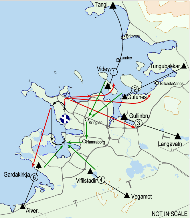
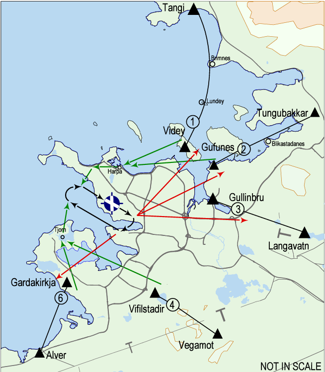
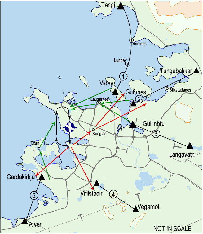
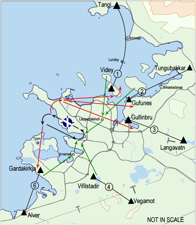
VATSIM pilots are often unfamiliar with these inbound and outbound routes. Therefore, while not required, it can often be helpful to explicitly describe the inbound/outbound route to the pilot, for example "from Vifilstadir join base runway 31."
Special Airspace
There are several special airspace areas in Iceland, including recreational, training, prohibited, and restricted areas. In general, most are uncontrolled, but some are near or underly controlled airspace.
For aircraft flying to such areas, one may adapt typical VFR phraseology as needed. For example:
🎧 (TF-)ISN, right turn towards Austursvaedi, 1500ft, winds 170 degrees 8 knots, Runway 19, cleared for takeoff.
Some regions require ATC approval to enter. In such cases, provided there is no reason the aircraft may not enter that airspace, TWR may tell aircraft they are “cleared to enter [NAME OF AREA]”
Once the aircraft is approaching a special airspace area, then one should:
- Tell them “frequency change approved.” This means they should monitor UNICOM, as well as maintain listening watch on any other frequencies as required by some restricted areas
- Add appropriate text to the ATIS as required by local operating procedures to indicate that traffic is active in that area. E.g., "GLIDERS OPERATING AT SANDSKEID."
- Coordinate with relevant neighboring ATC (e.g., TWR with APP) to notify them of traffic known to be in certain areas.
See the Iceland AIP, ENR 5 (particularly 5.1 and 5.2) for information regarding such areas.
BIKF | Keflavik Int'l
Local operating procedures for BIKF. (Aerodrome only – see Faxi TMA chapter for APP procedures.)
General
Keflavik Int'l Airport (BIKF) is the main international airport serving Iceland. The gateway to Iceland, it receives a wide variety of international traffic, as well as some domestic traffic. As a result, it is the most heavily trafficked airport in Iceland, both in real life and on VATSIM.
Runway Information
|
Runway |
RWY Dimensions |
Heading |
Approach Rating |
|
10 |
3065 x 60 |
104 |
CAT II |
|
28 |
3065 x 60 |
284 |
CAT I |
|
01 |
3054 x 60 |
014 |
CAT I |
|
19 |
3054 x 60 |
194 |
CAT II |
List of ATS Positions
| Coordination Name | VATSIM Logon | Radio Callsign | Frequency |
| Keflavik Delivery (KFD) | BIKF_DEL | “Keflavik Delivery” | 121.000 |
| Keflavik Ground (KFG) | BIKF_GND | “Keflavik Ground” | 121.900 |
| Keflavik Ground/Tower 2 (KFX) | BIKF_2_GND | “Keflavik Ground/Tower” | 126.200 |
| Keflavik Tower (KFT) | BIKF_TWR | “Keflavik Tower” | 118.300 |
| Keflavik ATIS (/KF) | BIKF_ATIS | — | 128.300 |
Login Priority
All positions may be opened at any time, except BIKF_2_GND, which may only be opened with the permission of BIKF_GND or BIKF_TWR (depending on if BIKF_2_GND is performing Tower or Ground responsibilities.)
Keflavik DEL
Keflavik Delivery (BIKF_DEL) shall provide clearance delivery to departing IFR aircraft.
As of 20th March 2024, all departing aircraft shall receive a standard IFR clearance; no oceanic clearances are to be issued.
Overview of SIDs
All SIDs below require RNAV 1 capability.
|
TERMINATING FIX |
RUNWAY |
|||
|
01 |
10 |
19 |
28 |
|
|
LUTER |
2A |
2B |
3C |
3D |
|
OSKUM |
3A |
1B |
3C |
3D |
|
PIXUM |
1A |
1B |
2C |
2D |
|
RIMUM |
1A |
3B |
1C |
1D |
|
DELES |
2A |
3B |
2C |
3D |
|
SORIR |
3A |
3B |
2C |
2D |
|
RALOV |
3A |
4B |
3C |
1D |
|
Initial Climb: FL290 (or RFL if lower) |
||||
Omnidirectional Departures
Aircraft which are non-RNAV may be cleared on the Omnidirectional (OMNI) departures. There are four OMNI departures – one for each runway. These departures essentially have the aircraft fly runway track to 5000ft, after which they will proceed as instructed by ATC. The initial climb is 5000ft.
|
RWY |
OMNI |
TRK |
|
01 |
4A |
014 |
|
10 |
4B |
104 |
|
19 |
4C |
194 |
|
28 |
4D |
284 |
When assigning an Omnidirectional departure, DEL shall notify APP (no prior approval from APP is required), and change the SID item in the Departure list to the appropriate OMNI SID, overriding Euroscope’s automatic SID selection.
An example of a clearance via an OMNI departure is as follows:
🎧 BAW80KA, cleared to London Heathrow via the Omnidirectional 4A departure, initial climb 5000ft, Mach .78, squawk 4301.
If the pilot appears unfamiliar with the OMNI departures, the alternative phraseology "after departure runway XX fly runway heading" may be used.
Standard Routings for Departures
Iceland AIP ENR 1.8.3.1.3.7 defines standard routing requirements for departures from BIKF. For ease of reference, they are summarized in the following images:
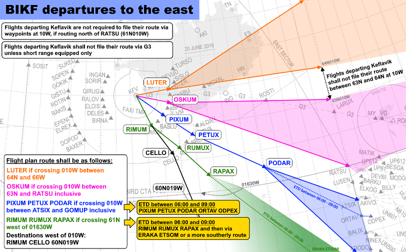

G3 Airway Restriction
For aircraft departing BIKF (and BIRK), the G3 airway is not available, except to aircraft with short-range navigational equipment only (e.g., VOR navigation.)
If an aircraft has filed a flight plan routing via G3, they should be rerouted as per the standard routings above.
Generally speaking, most aircraft may be rerouted from the last waypoint of their SID direct to either LUTER or PIXUM, followed by their final waypoint in the Reykjavik CTA.
For flights remaining in the Reykjavik CTA for their entire flight, such as those going to EKVG, the "final waypoint in the Reykjavik CTA" is simply the final waypoint of their flight plan.
IFR Flights to BIRK
DEL shall coordinate all IFR flights from BIKF to BIRK prior to issuing the clearance. APP should provide either a direct to one of BIRK’s Initial Approach Fixes (IAFs), or radar vectors, as appropriate for the traffic situation. Generally, such flights will rarely climb higher than 5000ft.
Such clearances follow the general format of non-standard clearances (see Delivery SOP page.) For example:
🎧 ICE9302, cleared to Reykjavik, after departure runway 19 proceed direct MIKVU, initial climb 5000ft, squawk 1371.
IFR Circuits/Crosswind Testing
In real life, BIKF is a common destination for aircraft manufacturers to test their aircraft’s heavy crosswind capabilities.
DEL must coordinate all such aircraft with APP prior to issuing any clearance. The flight may be issued a clearance with the clearance limit of “Keflavik,” specifying that the flight is performing IFR circuits (or crosswind testing), with any relevant departure instructions as coordinated with APP. For example:
🎧 BOE1, cleared to Keflavik, IFR circuits, after departure runway 19 climb straight ahead to 5000ft, squawk 1322.
Keflavik GND
Keflavik Ground (BIKF_GND, as well as BIKF_2_GND if online) is responsible for controlling the aprons and taxiways at BIKF.
Parking Locations
There are two main distinct parking areas on the aerodrome:
- Terminal Apron, also known as the "North Apron." There are two distinct sub-areas of the Terminal Apron:
- Maintenance Area – This is a separate small apron on the Western end of the complex.
- Terminal Remote East Apron - This recently opened remote parking expansion consists of the area east of N13 holding point.
- East Apron - Primarily a freight and large aircraft apron, also used for business jets (the Southern end of the East Apron hosts the FBOs) and helicopters.
Not all sceneries will have the Terminal Remote East Apron, or some of BIKF's newer taxiways such as Taxiway M and M1.
There is also the Western Complex, which is used exclusively by military fast jets operating in support of the Icelandic Air Policing mission.
The following table describes specific parking locations for specific types of flights.
|
Flight Type |
Parking Location |
|
Scheduled Passenger (Schengen Area) |
Stands 1-6 (Terminal Apron) |
|
Scheduled Passenger (Other) |
Stands 7-14 (Terminal Apron)* Terminal Remote East Apron |
|
Cargo |
Terminal Remote West Apron East Apron |
|
General Aviation |
East Apron |
|
Military |
Western Complex |
Note:
- Aircraft larger than Class D with a wingspan of 171’/52m or more are not allowed to taxi via S1 to and from the East Apron, and south of stand 111 on the East Apron.
- Aircraft parked on stands 11 & 14 must push back onto taxiway N.
- De-icing, if required, takes place on stand.
- There is a run-up area on a pad connected to taxiway N3/N2.
- There is a run-up area on a pad connected to taxiway N3/N2.
Terminal Apron
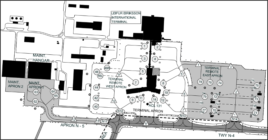
Entry Points
There are three entry points into the Terminal Apron – N12, N13, and N14. For aircraft entering the Terminal Apron, GND may specify which entry point the aircraft should leave or enter the apron from – e.g., “taxi via N12, N…” (can be helpful, but is not required.)
Departing aircraft leaving the apron should be instructed to hold short of N12/13/14 if N itself is occupied by conflicting taxiing traffic. Similarly, arriving aircraft may be instructed to give way to aircraft entering N from N12/13/14.
Tug Release Points
The Terminal (North) Apron uses tug release points for pushback. Aircraft pushing back on the North Apron will be towed to their designated tug release points.
|
Stand(s) |
Release Point |
Overflow Release Point |
|
1, 3, 5, 7, 44, 46 |
9 |
10 |
|
9, 40, 42 |
10 |
9 or 11 |
|
11, 14 |
8* *Aircraft may be instructed to face East or West depending on expected taxi route after pushback. |
|
|
8 |
6 |
4 (size category C only) |
|
62, 63, 65 |
12 or 11 |
|
|
10, 79 |
6 |
7 |
|
12, 77 |
7 |
6 |
|
76, 78 |
4 |
3 or 2 |
|
74 |
3 |
2 or 4 |
|
70, 71, 72, 73 |
1 |
2 |
|
75 |
2 |
1 |
|
55, 57, 59, 61 |
13 |
n/a |
Aircraft must not be cleared to push to a tug release point that is occupied. If the standard release point is occupied, GND should use the overflow release points in the order listed above.
GND should state the tug release point in the push & start clearance. For example:
🎧 ICE502, push & start approved, release point 5, QNH 1024.
NOTE: Some pilots, particularly in older simulators, may not have the ability to push to a specific release point. If this is the case, then GND may clear the aircraft for pushback without specifying a tug release point. GND should be cautious of other traffic that is taxiing or pushing back.
A380 Ground Movement
Due to the massive size & wingspan of A380s, specific taxiways have been designated for A380 ground movement.
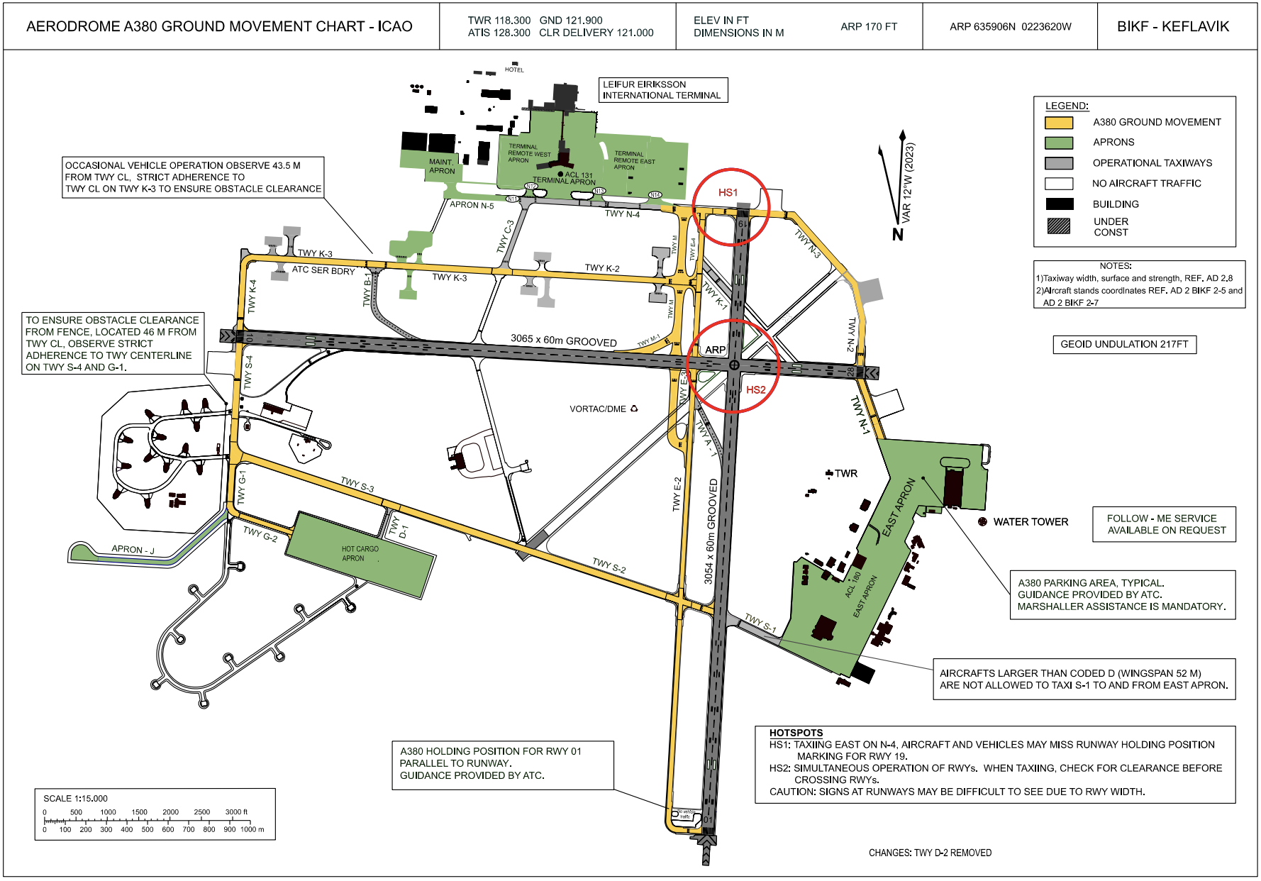
A380s may only be taxied on the yellow taxiways marked above, and should only be parked at the A380 parking area on the East Apron (stand 120.) A380s are also expected to use the A380 holding position for RWY 01, parallel to the typical E1 holding point for RWY 01 (see bottom of the chart).
Controllers may also consider strategically taxiing or backtracking aircraft via the runways to shorten A380s’ taxi distance.
Secondary GND Position
BIKF has an overflow aerodrome frequency, which for VATSIM purposes has the login callsign BIKF_2_GND.
BIKF_2_GND may relieve any of the responsibilities of either BIKF_GND or BIKF_TWR. E.g., it may take over apron control while BIKF_GND controls the taxiways. BIKF_2_GND may only be opened with the approval of the existing BIKF_GND (if performing Ground responsibilities) or BIKF_TWR (if performing Tower responsibilities) controllers.
BIKF_2_GND may adopt the callsign “Keflavik Ground” or “Keflavik Tower,” depending on whether it is performing Ground or Tower responsibilities.
Keflavik TWR
Keflavik Tower (BIKF_TWR) is responsible for BIKF’s runways, and for providing ATC service in the Keflavik Control Zone (BIKF CTR.)
Runway Configuration
Preferred Runways
RWY 01/19 is preferred for noise abatement. Therefore, if the tailwind component for RWY 01 or 19 is less than 5 KTS, TWR shall designate RWY 01 or 19 as the active runway.
When the tailwind component exceeds 5 KTS for RWY 01 or 19, TWR shall revise the runway configuration to use whichever runway has the strongest headwind component as the active runway.
Additionally, landing RWY 10 and departing RWY 28 may be approved at pilot request (traffic permitting) for noise abatement.
Low Visibility Runways
Additionally, note that RWYs 10 & 19 are CAT II equipped, and therefore they are the only runways usable for landing when Low Visibility Procedures (LVP) are in effect. See the Low Visibility Procedures page for more information.
Dual Runway Operations
During periods of heavy traffic, Keflavik Tower may, in coordination with Keflavik Approach, implement dual runway operations at BIKF. There are two variations of dual runway operations:
- Upon Request: Designating one runway as the active runway, but permitting departures/arrivals on the other runway on request.
- Dual Operations: Using one runway for all arrivals, and the other for all departures.
During such operations, Keflavik Tower & Keflavik Ground shall keep in mind the following:
- Whenever both runways are active (whether for a one-off departure or arrival, or indefinitely), any blanket crossing clearances automatically become invalid. GND must not instruct aircraft to cross any runway if TWR has not cleared that individual aircraft to do so.
- Departing aircraft must not be cleared to take off until any landing aircraft on the intersecting runway have cleared the departing runway fully.
- TWR may verify this visually without coordinating with GND.
- TWR may verify this visually without coordinating with GND.
Keflavik Control Zone (BIKF CTR)
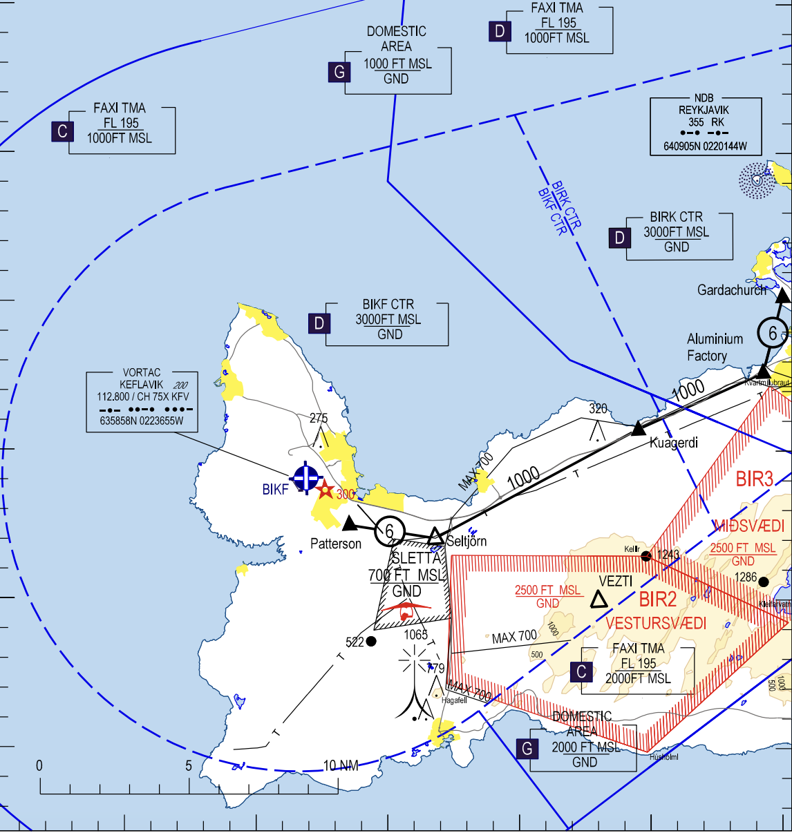
The BIKF CTR ranges from GND – 3000ft. It is directly bordered by the Reykjavik Control Zone (BIRK CTR) to the east, and is surrounded by the Faxi TMA above and to the sides.
Traffic Circuit
The standard traffic circuit for BIKF is west of RWY 01/19, and south of RWY 10/28. In other words, the turn direction of the circuit is Left for RWY 01 & 28, and Right for RWY 10 & 19.
The standard circuit altitude is 1200ft.
VFR Route 6
There is only one VFR route in the BIKF CTR for single-engine aircraft – route 6 to/from BIRK (named “Straumsvik”) at 1000ft. See the VFR Guide for more information.
VFR departures not on a VFR route should be instructed to report 12 NM out from BIKF. They should be coordinated with either Reykjavik Tower or Keflavik/Reykjavik Approach if they will be entering the BIKF CTR or Faxi TMA, prior to them reaching the relevant airspace boundary.
If an aircraft will not enter the BIKF CTR, and will remain below the Faxi TMA, it may be released to UNICOM without coordination.
Overlying Airspace: The Faxi TMA
The airspace directly overlying the BIKF CTR is the Faxi TMA. The Faxi TMA has “collars” (formerly known as "buffer zones") next to the BIKF CTR which extend down to 1000ft and 2000ft respectively – see the image below:
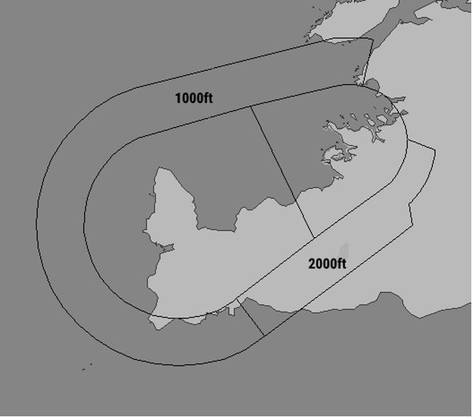
TWR should coordinate VFR aircraft leaving the CTR, including the collars, with APP. If a departing aircraft will only briefly enter the buffer zone without entering the TMA itself, and there is no conflicting IFR traffic, APP may simply have TWR release the aircraft to UNICOM.
Special Airspace
Neighboring restricted & training areas include Sandskeid, Sletta, and for the duration of the volcanic eruption on Reykjanes Peninsula, danger area BIR4. When there is activity in these areas, Tower should notify aircraft in the vicinity and add appropriate text to the ATIS, e.g., "GLIDERS OPERATING AT SANDSKEID."
Missed Approach
TWR shall instruct aircraft to follow the standard missed approach. If an aircraft is unable to fly the standard missed, TWR shall instruct them to climb straight ahead to 3000ft.
TWR shall coordinate all missed approaches with APP prior to transferring them to APP.
Next ATS Unit for Departures
Generally, all IFR departures should be transferred to Keflavik APP (BIKF_APP), or whoever is covering it top-down.
If both Keflavik and Reykjavik APP are online, then TWR should transfer the aircraft to whichever APP sector the aircraft will be entering the airspace of first. If in doubt, confirm with Keflavik APP.
Reduced Runway Separation Minima
The use of reduced runway separation minima (RRSM) is permitted at BIKF, subject to the conditions outlined in the Tower SOP.
Low Visibility Procedures
At BIKF, Low Visibility Procedures (LVP) come into effect when either the ceiling or the touchdown RVR have reduced to the point that ground visibility is affected.
The touchdown RVR for each runway may be found at the BIKF AWOS (Automated Weather Observing System) webpage, here: awos.kefairport.is/Map.aspx
LVP is enacted in four phases.
1. Preparation Phase
When the touchdown RVR reaches 800m and/or the ceiling is 300ft or less.
- TWR and APP shall coordinate to revise the runway configuration to land on either RWY 10 or 19 (only those two runways are CAT II equipped.)
- Departures may continue on RWY 01 or 28.
- ATC may not give conditional taxi instructions.
- Increased separation (at least +2nm) should be given between all departures and arrivals.
2. Activation Phase
When the touchdown RVR is less than 550m and/or the ceiling is 200ft or less.
GND & TWR should notify all aircraft upon first contact that low visibility procedures are in effect. The following text should also be added to the ATIS: “LOW VISIBILITY PROCEDURES IN EFFECT.” (The Euroscope ATIS generator set up in the sector file should do this automatically.)
When RVR is less than 550m, only one aircraft is allowed to move in the maneuvering area at once. This will severely limit airport capacity, to around 10 movements per hour.
3. Deactivation Phase
When touchdown RVR increases to 550m or more and ceiling is higher than 200ft.
- TWR & APP should coordinate to determine if the runway configuration should be revised when the visibility has improved.
4. Termination Phase
When touchdown RVR is 800m or more, the ceiling is above 200ft, and the conditions are expected to continue to improve.
At this point, LVP is no longer in effect, and normal operations may resume.
BIRK | Reykjavik
Local operating procedures for BIRK. (Aerodrome only – see Faxi TMA chapter for APP procedures.)
General
Reykjavik Airport (BIRK) is the second-largest airport in Iceland. It mainly handles domestic scheduled operations, as well as general aviation.
Runway Information
|
Runway |
RWY Dimensions (m) |
Heading |
|
01 |
1567 x 45 |
010 |
|
19 |
1567 x 45 |
190 |
|
13 |
1230 x 45 |
131 |
|
31 |
1230 x 45 |
311 |
List of ATS Positions
|
Coordination Name |
VATSIM Logon |
Radio Callsign |
Frequency |
|
Reykjavik Ground (RKG) |
BIRK_GND |
“Reykjavik Ground” |
121.700 |
|
Reykjavik Tower (RKT) |
BIRK_TWR |
“Reykjavik Tower” |
118.000 |
|
Reykjavik ATIS (/RK) |
BIRK_ATIS |
— |
128.100 |
Login Priority
All positions may be opened at any time.
Reykjavik GND
Reykjavik Ground (BIRK_GND) provides clearance delivery and ground control.
As of 20th March 2024, all departing aircraft shall receive a standard IFR clearance; no oceanic clearances are to be issued.
Delivery
Overview of SIDs
|
TERMINATING FIX |
RUNWAY |
|||
|
01 |
19 |
31 |
13 |
|
|
EL Ellidavatn/Elliðavatn |
1 |
2 |
3 |
4 |
|
KFV Keflavik |
1 |
2 |
3 |
4 |
|
MYRAR |
1 |
2 |
3 |
4 |
|
Initial Climb: FL290 (or RFL if lower) |
||||
The EL (Ellidavatn) departures may terminate at several fixes – EL, REKVA, TIBRA, LUTER, or METIL. It is not required to state the terminating fix in the IFR clearance, assuming said fix was already in the aircraft’s flight plan.
If one changes the terminating fix, then one should specify the new terminating fix in the clearance (e.g., “Ellidavatn 2 departure, direct LUTER.”)
Standard Routings for Departures
Iceland AIP ENR 1.8.3.1.3.7 defines standard routing requirements for departures from BIRK. For ease of reference, they are summarized in the following images:

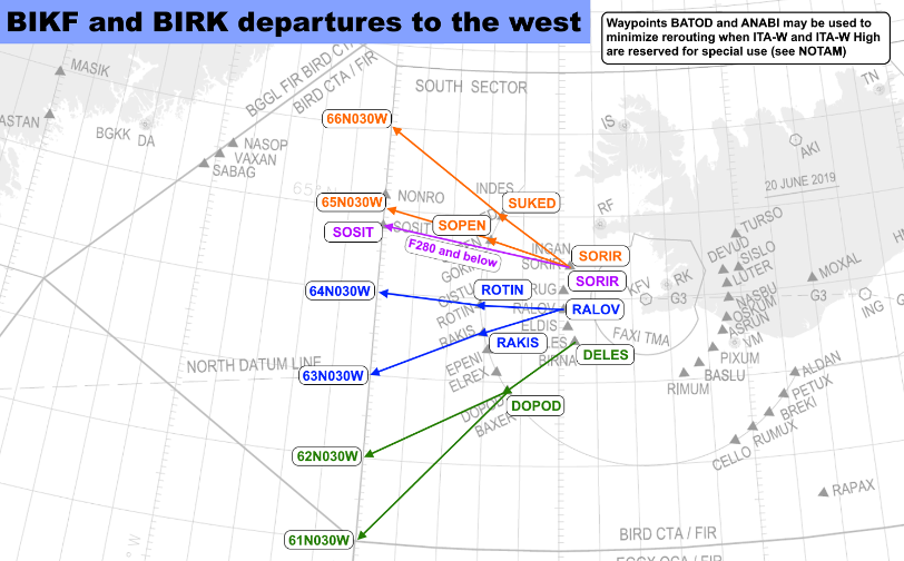
G3 Airway Restriction
For aircraft departing BIRK (and BIKF), the G3 airway is not available, except to aircraft with short-range navigational equipment only (e.g., VOR navigation.)
If an aircraft has filed a flight plan routing via G3, they should be rerouted as per the standard routings above.
IFR Flights to BIKF
DEL shall coordinate all IFR flights from BIRK to BIKF prior to issuing the clearance. APP will provide either a direct to one of BIKF's Initial Approach Fixes (IAFs), or radar vectors, depending on the traffic situation.
Such clearances follow the general format of non-standard clearances (see Delivery SOP page), for example:
🎧 ICE9303, cleared to Reykjavik, after departure runway 19 direct ELVUM, initial climb 5000ft, squawk 1317.
Ground
Parking Locations
|
Flight Type |
Parking Location |
|
Scheduled Passenger |
Apron 4 ("North Apron") Apron 1 (Arctic Eagle / FEI only) |
|
General Aviation / Charter Passenger |
Fluggardar (Hangars 21-37) Apron 1 ("East Apron" – includes FBO) Apron 7: Icelandic Flight Academy Apron/Hangar 3 (Heli) |
|
Coast Guard (ICG) |
Apron/Hangar 2 |
All aprons EXCEPT Fluggardar are controlled. Fluggardar is uncontrolled.
Run Up Areas
At BIRK, there are two unmarked run-up areas. One is located east of Hangar 4 (east of taxiway G on Apron 4), and one is located to the west of Hangar 8 (on Apron 1).

The first run-up location is generally used by aircraft coming from Fluggardar, and the second is generally used by aircraft coming from Aprons 1/7.
Aircraft requesting run-up may be taxied “to Hangar [4/8] for run-up.”
Reykjavik TWR
Reykjavik Tower (BIRK_TWR) is responsible for BIRK’s runways, and for providing air traffic control service within the Reykjavik Control Zone (BIRK CTR.)
Runway Configuration
Controllers should consider that RWY 01/19 is considerably longer than RWY 13/31 (1567 vs 1230m). Moreover, only RWY 19 has an ILS (RWY 13 only has a localizer, and RWYs 01 and 31 have no precision landing equipment.)
Therefore, while there is no "general" preferred runway, heavier aircraft such as turboprops and jet airliners may prefer or even require RWY 01/19, even if the winds slightly favor RWY 13/31.
Reykjavik Control Zone (BIRK CTR)
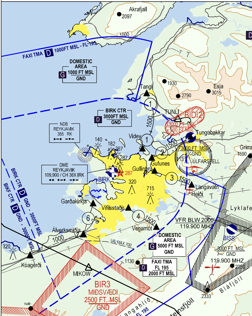
The BIRK CTR ranges from GND – 3000ft. It is directly bordered by the Keflavik Control Zone (BIKF CTR) to the west, and is surrounded by the Faxi TMA above and to the sides.
Traffic Circuit
The standard traffic circuit for BIRK is south of Runway 13/31, and west of Runway 01/19. Therefore, the circuit direction is Left for RWY 01 & 31, and Right for RWY 13 & 19.
VFR Routes
Five VFR routes are published within the CTR for single-engine VFR aircraft – routes 1, 2, 3, 4, and 6 (route 5 is not in use). See the VFR Guide for more information.
VFR departures not on a VFR route should be instructed to report 6 NM out from BIRK. They should be coordinated with either Reykjavik Tower or Keflavik/Reykjavik Approach if they will be entering the BIRK CTR or Faxi TMA, prior to them reaching the relevant airspace boundary.
If an aircraft will not enter the BIRK CTR, and will remain below the Faxi TMA, it may be released to UNICOM without coordination.
Overlying Airspace: The Faxi TMA
The airspace directly overlying the BIKF CTR is the Faxi TMA (Terminal Manoeuvring Area). Specifically, the Keflavik (KF) sector of the Faxi TMA directly overlies the BIRK CTR. Moreover, the Faxi TMA has “buffer zones” next to the BIRK CTR which extend down to 1000ft and 2000ft respectively. See the image below.
TWR should coordinate VFR aircraft leaving the CTR into the TMA, including the collars, with APP. If a departing aircraft will only briefly enter the buffer zone without entering the TMA itself, and there is no conflicting IFR traffic, APP may simply have TWR release the aircraft to UNICOM.
Special Airspace
Neighboring restricted & training areas include Sandskeid, Sletta, and for the duration of the volcanic eruption on Reykjanes Peninsula, danger area BIR4. When there is activity in these areas, Tower should notify aircraft in the vicinity and add appropriate text to the ATIS, e.g., "GLIDERS OPERATING AT SANDSKEID."
Missed Approach
TWR should instruct aircraft to follow the standard missed approach. If an aircraft is not able to fly the standard missed, TWR should instruct the aircraft to climb straight ahead to 5000ft, or coordinate appropriate vectors with APP.
TWR shall coordinate all missed approaches with APP prior to transferring them to APP.
Clearance Below 2000ft (VFR / Visual App)
Twin- or multi-engine aircraft arriving BIRK which are VFR, or requesting a visual approach, must be cleared below 2000ft by Reykjavik TWR. APP shall coordinate all aircraft with TWR prior to transfer of control; if TWR grants the clearance below 2000ft, then APP may communicate that to the pilot.
In the rare circumstance that traffic congestion in the CTR/circuit do not permit giving clearance below 2000ft as described above, TWR must provide the aircraft alternate instructions (e.g., orbiting/holding away from the airport.) Alternatively, TWR may deny the aircraft permission to enter the CTR.
Next ATS Unit for Departures
Generally, all departures should be transferred to Keflavik APP (BIKF_APP) after departure.
If both Keflavik and Reykjavik APP are online, then TWR should transfer the aircraft to whichever APP sector the aircraft will be entering the airspace of first. If in doubt, confirm with Reykjavik APP.
Reduced Runway Separation Minima
The use of reduced runway separation minima (RRSM) is permitted at BIRK, subject to the conditions outlined in the Tower SOP.
NOTE: Due to the airport layout at BIRK often requiring backtracks, and the shortness of the runways, controllers may find it difficult to obtain the necessary separation distances to apply RRSM.
BIAR | Akureyri
Local operating procedures for BIAR.
General
NOTE: BIAR requires a Tier 2 endorsement to control.
Akureryi Airport (BIAR) is located in the northern part of Iceland. Akureyri accepts domestic flights from across Iceland, as well as a limited selection of international flights.
Runway Information
|
Runway |
RWY Dimensions (m) |
Heading |
|
01 |
2400 x 45 |
007 |
|
19 |
2400 x 45 |
187 |
List of ATS Positions
|
Coordination Name |
VATSIM Logon |
Radio Callsign |
Frequency |
|
Akureyri Tower (ART) |
BIAR_TWR |
“Akureyri Tower” |
118.200 |
|
Akureyri ATIS (/AR) |
BIAR_ATIS |
— |
136.200 |
Logon Priority
All positions may be opened at any time.
Akureyri TWR
Akureyri Tower (BIAR_TWR) provides clearance delivery, ground, and tower control.
As of 20th March 2024, all departing aircraft shall receive a standard IFR clearance; no oceanic clearances are to be issued.
This page only covers the "normal" aerodrome-level procedures for BIAR. For information on the procedural approach service which Akureyri TWR also provides, see the Procedural Approach page.
Delivery
Overview of SIDs
|
END FIX |
RWY 01 |
RWY 19 |
|
AR (Akureyri NDB) |
1A |
|
|
AKI (Akureyri VOR) |
2A, 2B |
|
|
ASKUR |
1A*, 1B* |
1C**, 1D, 1E |
|
MAMEP |
1A* |
|
|
JARRI |
|
1C**, 1D, 1E |
|
PERUR |
1A* 1B* |
1D |
|
RETUR |
|
1D** |
|
UTISU |
2A* |
|
* Only category A and B aircraft.
** Only category A, B, and C aircraft.
As indicated above, several of BIAR’s SIDs are restricted to only aircraft of certain performance categories. Aircraft incapable of meeting the performance requirements for a given SID should be assigned an appropriate alternative, or as a last resort, may be issued a visual climb.
Ground
There is only one apron, and one taxiway (taxiway A) that leads to/from the runway. When managing a combination of departures and arrivals, it may be beneficial to tactically utilize backtracking to allow departures to line up while arrivals make a U-turn to exit the runway.
Tower
Traffic Circuit
The standard traffic circuit is a right-hand circuit for runway 01, and a left hand circuit for runway 19. I.e., the circuit is always East of the runway.
Akureyri Control Zone (BIAR CTR)
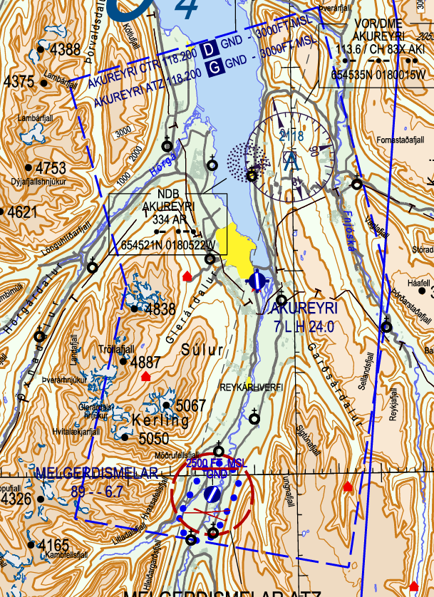
The Akureyri CTR has a lower limit of GND and an upper limit of 3000ft.
In real life, the Akureyri CTR reverts to Class G and becomes the Akureyri ATZ outside the operating hours of Akureyri TWR. On VATSIM, since we simulate that Akureyri TWR is operating whenever anyone is controlling it/covering it top-down, the Akureyri CTR is always active as Class D airspace.
The Akureyri TMA (also controlled by Akureyri Tower; see chapter 3.4) overlies the CTR.
The recreational airfield BIMM (Melgerðismelar – “Melgerdismelar”) exists within BIAR CTR, and has an associated recreational airspace area. This airfield is often used for ultralight and recreational gliding operations. Aircraft within the vicinity of BIMM shall monitor BIAR TWR’s frequency.
There are no officially defined VFR routes or reporting points.
- In real life, TWR may ask aircraft to report passing Hrafnagil (a village south of Akureyri) when entering the CTR from the South (or leaving to the South), or Svalbarðseyri (a village north of Akureyri, on the east side of the fjord) when entering the CTR from the North (or leaving to the North).
- However, VATSIM pilots may not necessarily be familiar with these locations. Therefore, Akureyri Tower on VATSIM is not expected to use these points, and may simply instruct aircraft to “report leaving/approaching the control zone.”
Reduced Runway Separation Minima
The use of reduced runway separation minima (RRSM) is permitted at BIAR, subject to the conditions outlined in the Tower SOP.
Due to the airport layout at BIAR often requiring backtracks, and the short length of the runway, controllers may find it difficult to obtain the necessary separation distances to apply RRSM except with light aircraft.
Procedural Approach
Akureyri Tower is unique within Iceland, in that it is the only TWR unit which also provides an approach control service within the Akureyri TMA.
Akureyri TMA
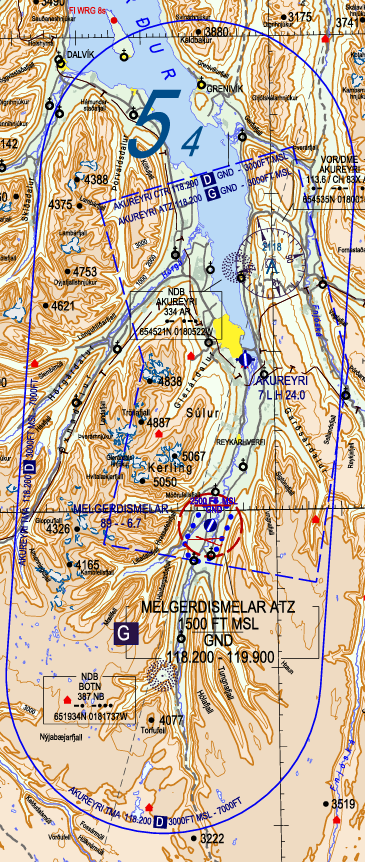
The Akureyri TMA has a lower limit of 3000ft and an upper limit of 7000ft. It overlies the Akureyri CTR, and is surrounded by the Class E airspace of Reykjavik ACC. It is Class D airspace.
In real life, outside of the operating hours of Akureyri Tower, the TMA reverts to Class E airspace and is controlled by Reykjavik ACC. However, on VATSIM, we simulate Akureyri Tower as being in operation whenever anyone is controlling the position, so for all intents and purposes the airspace is always Class D.
Primary Surveillance Radar (PSR)
Primary surveillance radar (PSR) is available within Akureyri TMA.
Akureyri TWR may use PSR to stay situationally aware of traffic in their airspace. However, Akureyri TWR shall at all times adhere to procedural separation minima, and may not vector aircraft or apply radar separation minima. The only exception is when Akureyri TWR is providing a surveillance radar approach service (LOC/ASR approach; see below.)
IFR Arrivals
Upon first contact, TWR shall give all aircraft the local QNH.
STAR/Initial Approach
Runway 19
Runway 19 at BIAR has published STARs. Reykjavik ACC clears aircraft onto the STAR and descends them to 7000ft, then transfers the aircraft to TWR prior to them commencing the STAR. Upon first contact, TWR will issue further descent to 6000ft.
There are some STARs with the same starting fix but different routings (e.g., MAMEP1M and MAMEP1N.) In these cases, the "M" STAR is preferred (i.e., MAMEP1M), as it connects directly to the ILS approach for RWY 19.
If Reykjavik is offline, then TWR may send a “contact me” to the aircraft before they reach the STAR's first waypoint. TWR may then issue clearance onto the STAR and descent to 6000ft. For example:
🎧 ICE200, Akureyri Tower, cleared AFPAC 1M arrival, descend 6000ft, QNH 1014.
Runway 01
Runway 01 has no published STARs. Therefore, aircraft generally proceed directly to the IAF for the instrument approaches — NB, GILTU, or PEXIL.
On first contact, aircraft should be descended to the initial approach altitude for their intended approach type and IAF, and given the local QNH. The initial approach altitudes for each IAF and approach are as follows:
|
BIAR RWY 01 Initial Approach Altitudes |
|||
|
|
Approach Type |
||
|
IAF |
ILS |
LOC |
LOC A |
|
NB |
6100’ |
6500’ |
|
|
GILTU |
— |
6800’ |
|
|
PEXIL |
6000’ |
— |
|
For more information on BIAR's approaches, see below.
Final Approach
As a general principle, to ensure procedural separation, only one aircraft may be on initial approach (between the IAF and being established on final approach) at once. In other words:
- If there is no traffic ahead on approach, TWR may clear aircraft onto the approach.
- If there is traffic ahead that is not yet established on final approach, then TWR must instruct further arrivals to hold.
- Only after the traffic ahead is established on final approach may TWR clear further aircraft onto the approach.
Approach clearance generally follow the format: Via [IAF], cleared [APPROACH] runway XX, report [established/final approach track]. For example:
🎧 ICE500, via NORFI, cleared ILS approach runway 19, report established.
🎧 ICE501, via GITTA, cleared RNP X approach runway 19, report established on final approach track.
Generally, "report established" is used for ILS approaches, "report established on final approach course" is used for LOC, VOR, and NDB approaches, and "report established on final approach track" is used for RNAV/RNP approaches.
Runway 19
There are two instrument approaches mainly used for runway 01: the ILS and the RNP X approaches. They are assigned depending on which STAR the aircraft is on:
- If the aircraft is on a STAR ending with the letter M, they should be cleared for the ILS approach.
- If the aircraft is on a STAR ending with the letter N, they should be cleared for the RNP X approach.
Runway 01
There are two main instrument approaches used for runway 01: the ILS and Localizer approaches.
The ILS approach is a straight-in ILS with a steep approach angle (5.3 degrees). In general, it is preferred; however, because of the steep approach angle, aircraft may occasionally require the Localizer approach.
The Localizer approaches into BIAR offer a less steep approach angle, but a lower precision and more challenging approach.
- Unlike most airports, BIAR’s localizer approach uses a different localizer beacon than the ILS approach. The localizer approach uses an offset localizer that follows the valley towards the airport, allowing for a less steep approach, but requiring a left turn on short final to line up with the runway.
- There are two localizer approaches – the LOC approach for aircraft categories A & B, and the LOC A approach for aircraft categories C & D.
- The two approaches are essentially identical in lateral routing, but the LOC approach (categories A/B aircraft) has a slightly less steep approach path. TWR is expected to clear aircraft onto the appropriate approach for their category.
NB/PEXIL are the IAFs for the ILS approach, and GILTU/NB are the IAFs for the LOC/LOC A approaches. Reykjavik Control will generally route aircraft directly to these fixes.
NOTE! The initial approach altitudes are subject to change, and are only provided here for reference. Always consult the current Iceland AIP for the most up-to-date approach altitudes.
Arrival Sequencing and Holding
If there are two or more arrivals at once, until the first aircraft has established onto the ILS/final approach track, no further aircraft may be cleared for approach. If the second aircraft reaches the IAF before the first aircraft is established onto final approach, the second aircraft must hold until the first aircraft is established.
The following IAFs have published holds: NORFI, ARLAX, and AKI. Their MHAs are:
- NORFI & ARLAX – 6000ft
- AKI – 5000ft
- NB – 6500ft
For aircraft approaching an IAF without a published hold (e.g., GITTA), TWR should re-route the aircraft to an IAF with a published hold to hold there. Aircraft should maintain at least 6000ft to ensure terrain clearance.
Published holds may be issued using the abbreviated phraseology: “Hold at [FIX] as published, [LEVEL].” For example:
🎧 ICE123, hold at ARLAX as published, 6000ft.
When issuing a non-published hold, or if a pilot requests the full details of the hold, the following information should be given at minimum:
- Holding fix
- Level
- Inbound track/course
The following may also be specified:
- Turn direction (left or right turns. If not specified, it is assumed that the holding shall use right turns.)
- Time/length of leg (in minutes or NM. If not specified, it is assumed that the holding shall use 1-minute legs.)
The following phraseology may be used: [CALLSIGN], hold at [FIX], [LEVEL], [INBOUND COURSE], [LEFT/RIGHT] turns, [LEG TIME/LENGTH]. For example:
🎧 ICE123, hold at NORFI as published, 6000ft, inbound course 159, right turns, one minute legs.
Because the MHA of all the holds are quite close to the upper limit of the TMA, combined with the small size of the TMA itself, there is a significant capacity constraint on the amount of aircraft Akureyri TWR may hold in the TMA at once.
If there is a substantial amount of arriving traffic (>4 in the TMA at once), TWR should coordinate with Reykjavik ACC to hold aircraft outside of the TMA.
Missed Approach
TWR should instruct aircraft to follow the standard missed approach. The standard missed approaches vary between runways and approaches, and should be strictly adhered to to maintain terrain clearance.
Once the aircraft has completed the missed approach procedure, they may be cleared direct to one of the approach IAFs to try the approach again.
If aircraft are unable to fly the standard missed, TWR should instruct the aircraft to perform a visual climb to an appropriate waypoint/beacon (e.g., AKI for RWY 01, or NB for RWY 19), climbing to 6000ft. The aircraft may then be cleared further direct to one of the IAFs.
Non-Standard Approaches
RNP Y / LOC Approaches (RWY 19)
These approaches for RWY 19 are very similar to the ILS approach, sharing the same IAFs and essentially the same lateral routing/vertical profile. They may thus be treated the same, simply substituting the appropriate phraseology (e.g., saying “RNP Y” or “Localizer” instead of “ILS.")
NDB Approach (RWY 19)
The NDB approach into BIAR is a “teardrop” procedure. The aircraft starts at AKI VOR, flies outbound, then makes a long right turn (>180 degrees) to fly inbound OE. After OE, the aircraft joins a short final for runway 19.
Aircraft on the NDB approach should be asked to report outbound from AKI, and then inbound OE. Once an aircraft is inbound OE, it is considered to be on final approach track, and further aircraft may be cleared for approach.
LOC/ASR Approach (RWY 01)
The LOC/ASR approach for runway 01 is a unique procedure which combines the offset localizer, which is used for initial approach, with a surveillance radar approach, which is used for the left turn to final. This is the only circumstance in which Akureyri Tower is authorized to issue instructions based on radar.
The procedure is as follows:
- Via NB or GILTU, the aircraft establishes onto the localizer, and descends like it would on a normal localizer approach.
- The aircraft shall report 12 DME out. At this point, TWR may radar identify the aircraft (i.e., look at their radar scope to determine which return corresponds to an aircraft 12 NM out from the localizer.)
- At 4.7 DME, TWR begins vectoring the aircraft, giving it heading instructions to line it up with the runway (starting with a heading of 007).
- TWR will instruct the aircraft not to acknowledge further transmissions from them.
- Starting from 4.0 DME, TWR will also provide pre-calculated advisory altitudes to the pilot.
- Once the aircraft is visual, the surveillance radar portion of the approach is completed, and the aircraft continues on a visual approach to the runway.
- If the aircraft has not reported visual by 2 DME, then they should be instructed to continue visually or go around.
When a LOC/ASR approach is in progress, TWR should be solely focused on issuing instructions to the aircraft on approach. Other aircraft should be instructed to hold, standby, etc. as appropriate.
Due to the complex nature of the approach, it is best demonstrated using an example:
🎧 ICE421, via GILTU, cleared LOC/ASR approach runway 19, report established on the localizer.
🧑✈️ Cleared LOC/ASR approach runway 19, wilco, ICE421.
…
🧑✈️ ICE421, established on the localizer.
🎧 ICE421, roger.
…
🧑✈️ ICE421, 12 DME.
🎧 ICE421, radar contact, this will be a surveillance radar approach for runway 01, terminating at 2 miles from touchdown, check your minima.
🧑✈️ Roger, ICE421.
🎧 ICE421, winds 330 degrees 10 knots, runway 01, cleared to land.
🧑✈️ Cleared to land, ICE421.
…
[Once the aircraft reaches 4.7 DME]
🎧 ICE421, turn left heading 007, report visual.
🧑✈️ Left heading 007, wilco, ICE421.
🎧 ICE421, do not acknowledge further transmissions.
…
🎧 ICE421, 4 miles from touchdown, altitude should be 1490 ft.
…
🎧 ICE421, 3.5 miles from touchdown, altitude should be 1310 ft.
…
🎧 ICE421, going left of track, turn left 2 degrees.
…
🎧 ICE421, closing slowly from the left, 3 miles from touchdown, altitude should be 1120 ft.
…
🎧 ICE421, turn right 2 degrees.
…
🎧 ICE421, on track, 2.5 miles from touchdown, altitude should be 940 ft.
…
🧑✈️ Visual, ICE421.
🎧 ICE421, on track 2 miles from touchdown, approach completed.
Some important phraseology to keep in mind when performing a LOC/ASR approach include the following (sourced from ICAO Doc 4444):
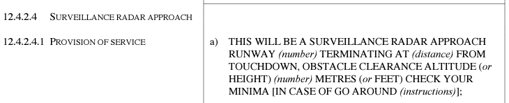
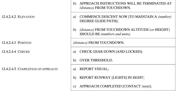
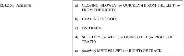
Departures
Generally, departures should be asked to report passing 7000ft, after which they may be transferred to Reykjavik Control. If the departure's flight path may cross the path of any arrivals, or if the flight path of the departure is not defined (e.g., it is on a visual climb), then TWR should hold arrivals until the departure has left the TMA.
VFR in the TMA
As Akureyri Tower is responsible for BIAR TMA, that means that Akureyri Tower is also responsible for VFR aircraft within the TMA.
VFR aircraft require clearance to enter the TMA. For example:
🎧 (TF-)ISN, cleared to enter the Akureyri TMA, 3500ft or below, QNH 1010.
BIAR TWR controllers are reminded that the TMA and the CTR are separate airspaces with different lateral and vertical boundaries. For example:
- Aircraft leaving the CTR below 3000ft will not enter the TMA, and therefore should be released to UNICOM as soon as they pass the CTR boundary.
- Similarly, aircraft crossing the TMA’s lateral boundaries below 3000ft are not within the TMA, and may remain on UNICOM until approaching the CTR (if inbound to BIAR.)
BIAR TWR controllers are also reminded that in Iceland, above 3500ft, VFR aircraft shall cruise at levels following the semi-circular rule (East = odd level, West = even level) plus 500ft.
- I.e., within the TMA, valid cruising levels for a VFR flight tracking Eastbound would be 3500ft or 5500ft, and valid cruising levels for a VFR flight tracking Westbound would be 4500ft or 6500ft.
The airspace surrounding the CTR (below 3000ft) is Class G (uncontrolled) airspace. Aircraft leaving the CTR without climbing above 3000ft should be instructed to monitor UNICOM.
The airspace surrounding the TMA (3000ft and above) is Class E airspace controlled by Reykjavik ACC. Reykjavik ACC may provide a flight information service upon request to VFR aircraft in this airspace, but is not required to do so.
- Hence, VFR aircraft leaving the TMA should be told “frequency change approved.” It is the pilot’s responsibility to either monitor UNICOM, or at their own discretion, change to the Reykjavik Control frequency to request FIS.
Faxi TMA (BIKF & BIRK APP)
Local operating procedures for Keflavik & Reykjavik Approach in the Faxi TMA.
General
The following page lists information and procedures applicable to the entire Faxi TMA, i.e., both Keflavik & Reykjavik Approach.
List of ATS Positions
|
Coordination Name |
VATSIM Logon |
Radio Callsign |
Frequency |
|
Keflavik Approach (KFA) |
BIKF_APP |
“Keflavik Approach” |
119.300 |
|
Reykjavik Approach (RKA) |
BIRK_APP |
“Reykjavik Approach” |
119.000 |
|
Keflavik Final (KFF) |
BIKF_F_APP |
“Keflavik Approach” |
119.150 |
Division of Responsibilities
The KF sector is controlled by Keflavik Approach, and the RK sector is controlled by Reykjavik Approach. If Reykjavik Approach is not online, Keflavik Approach bandboxes to cover Reykjavik Approach as well.
When both Keflavik & Reykjavik Approach are online, they operate as detailed in the "Dual Approach Operations" section below.
“Approach” or "APP" in this chapter, unless otherwise specified, refers to Keflavik Approach online by itself, bandboxing both sectors of the TMA and controlling arrivals and departures into both BIKF & BIRK.
Login Priority
Keflavik APP may be opened at any time. Reykjavik APP may only be opened if Keflavik APP is already online. Keflavik Final may only be opened with the approval of Keflavik APP.
Overview of the Faxi TMA

The Faxi TMA (3000ft/1000ft AGL— FL245) is located above Keflavik (BIKF) and Reykjavik (BIRK) airports. It is divided into two sectors – the Keflavik (KF) sector above BIKF, and the Reykjavik (RK) sector above BIRK.
Collars

The Faxi TMA also has "collars" (formerly known as "buffer zones") surrounding the BIKF & BIRK CTRs. Within these collars, the TMA is extended downwards to 1000ft or 2000ft MSL (depending on the section of the collar; see above.)
Airspace Classification
The Faxi TMA consists of Class A, Class C, and Class D airspace.
- The entire TMA is Class A above FL195.
- Below FL195:
- The KF sector is Class C.
- The RK sector is Class D.
The surrounding airspace is either Class A for the Oceanic Area directly above the TMA (FL245+), Class E for the Domestic Area surrounding the TMA (3000ft – FL245), or Class G for the airspace below 3000ft.
Minimum Horizontal Separation
The minimum horizontal separation in the Faxi TMA is 3 NM within 30 NM of KFV. This is a non-standard reduction of separation. Over 30 NM from KFV, the standard horizontal separation minima of 5 NM applies.
Minimum Vectoring Altitudes
Minimum radar vectoring altitude areas have been established in the Faxi TMA. These are indicated by the golden lines & text on the image above. Levels are indicated as hundreds (e.g., 41 = 4100ft).
Approach may not issue vectors or directs to aircraft which will cause them to violate the MVA areas.
Procedures
60 NM Release for Arrivals
Reykjavik transfers arrivals to Keflavik/Reykjavik APP when they are 60 NM from KFV VOR. Such arrivals are fully released.
Departures are transferred to Reykjavik Control at the TMA boundary (note: not at the 60 NM ring.)
Dual Approach Operations
When both Keflavik and Reykjavik APP are online at the same time, then they will each control their own respective sector of the TMA (KF sector for Keflavik APP, and RK sector for Reykjavik APP.)
This effectively means that BIKF arrivals from the East (via NASBU, ASRUN, etc.) will generally speak to Reykjavik APP first. Similarly, BIRK arrivals from the West (via INGAN, GIRUG, etc.) will generally speak to Keflavik APP first.
If Reykjavik APP has any BIKF-bound arrivals in their airspace, they shall transfer them to Keflavik APP no less than 10 NM from the IAF, or 20 NM from the aerodrome (whichever is greater.) This is to allow Keflavik APP sufficient time to issue the approach clearance. The same applies in reverse for any BIRK-bound arrivals in Keflavik APP's airspace.
- Such arrivals are released for descent and turn, unless otherwise coordinated.
Keflavik APP
Keflavik Approach (BIKF_APP) provides approach control service to all aircraft within the Keflavik (KF) sector of the Faxi TMA, and area control service to aircraft transiting the KF sector of the TMA. Keflavik APP also bandboxes the RK sector of the TMA when Reykjavik APP is offline.
Arrivals
|
INITIAL FIX |
RUNWAY |
|||
|
01 |
10 |
19 |
28 |
|
|
DEVUD |
4N |
4M |
2K |
1H |
|
NASBU |
4N |
2M |
3K |
1H |
|
ASRUN |
3N |
2M |
2K |
1H |
|
BASLU |
3N |
3M |
2K |
2H |
|
BIRNA |
2N |
3M |
3K |
2H |
|
ELDIS |
3N |
3M |
3K |
3H |
|
GIRUG |
3N |
3M |
2K |
2H |
|
INGAN |
5N |
3M |
2K |
2H |
Reykjavik Control clears aircraft for the STAR & descends them to FL100. If Reykjavik Control is offline, then APP may contact aircraft early (3-5 mins before they reach the first waypoint of the STAR) to issue STAR clearance and descent.
The standard approach for all runways is the ILS Z approach. BIKF's STARs are designed such that the last waypoint of the STAR is also one of the IAF of the ILS Z approach for that runway.
APP shall descend aircraft to cross the IAF at 3000ft if RWY 10/19 is in use, or 3500ft if RWY 01/28 is in use.
Traffic permitting, it is common practice for APP to cancel the STAR and clear aircraft directly to the IAF.
To ensure that no aircraft violates the minimum horizontal separation of 3 NM in the TMA, APP shall establish aircraft onto the ILS with no less than 5 NM separation. During single runway operations, APP should aim for 7 NM between arrivals, to ensure sufficient gaps for departures.
The ILS Z approaches have a published minimum speed of 160kts until 4 NM from the airport. APP may issue a higher/lower speed requirement, or cancel this speed restriction, as necessary for separation and sequencing.
Arrivals on the ILS Z or RNP approaches may be transferred to TWR as soon as they have passed the IAF. For any other approach, APP should wait until the aircraft is established on final approach track/course.
Missed Approach
TWR shall instruct aircraft to follow the standard missed approach, which is generally runway track to 3000ft (except for RWY 10, where it is runway track to D5.0 IKF and then left turn heading 328 climbing to 3000ft.)
If an aircraft is unable to fly the standard missed, TWR will instruct them to climb straight ahead to 3000ft.
TWR shall coordinate all missed approaches with APP prior to transferring them to APP.
Non-Standard Approaches
If aircraft are unable to accept the ILS Z approach, then alternative approaches should be offered in order of precision.
RNP & LOC Z
The published RNP & LOC Z approaches largely mirror the ILS Z approaches, and share the same published minimum speed of 160kts until 4 NM from the airport.
Vectored ILS
Aircraft on a vectored ILS approach into BIKF should be established no closer than 10 NM out.
ILS Y / VOR
The ILS Y and VOR approaches at BIKF are non-RNAV ILS procedures. They are teardrop-shaped procedures commencing from KFV VOR. Aircraft requesting these approaches should be cleared direct to KFV as soon as practical. After KFV, aircraft should report beacon outbound, and then established on the ILS/final approach course (as appropriate.)
Due to the added difficulty of sequencing aircraft on these procedures while the ILS Z/RNP approaches are also in use, it is preferred to vector aircraft onto the ILS instead of using these procedures.
Since the ILS Y and VOR approaches requires the aircraft to descend below 3000ft (into the BIKF CTR), APP should coordinate with Keflavik TWR to make them aware of any aircraft on such approaches.
NDB (RWY 10)
The NDB approach for RWY 10 is a racetrack procedure commencing from KF NDB. Aircraft may be cleared direct KF as soon as practical. The aircraft should be asked to report on final approach course, at which point it may be transferred to TWR.
Since the NDB approach requires the aircraft to descend below 3000ft (into the BIKF CTR), APP should coordinate with Keflavik TWR to make them aware of any aircraft on such approaches.
Departures
Upon identifying a departure, traffic permitting, APP may clear the aircraft direct to the last waypoint of the SID, even though the last waypoints of the SIDs are outside of the TMA.
- This does not require coordination with Reykjavik Control.
- If giving such a direct, APP should also reiterate the initial climb to FL290 (simply as “climb,” not “climb via SID,” since the SID is cancelled.)
E.g.,
🎧 ICE123, Keflavik Approach, identified, cleared direct OSKUM, climb FL290.
For OMNI departures, APP should clear the aircraft direct to the first waypoint of its flight plan, and issue further climb to FL290, as soon as practical.
LVP Operations
When BIKF is in LVP, Keflavik Approach and Keflavik Tower should coordinate to revise the runway configuration so that the arrival runway is either RWY 10 or 19, as those are the only two CAT II equipped runways at BIKF. Approach should ensure additional spacing (at least +2 NM on top of usual minima) between aircraft.
Final Approach Position (BIKF_F_APP)
The Final Approach position is intended to relieve the workload of the primary Approach position during high traffic. The coordination name of BIKF_F_APP is Keflavik Final (Keflavik FIN for short), and its radio callsign is “Keflavik Approach.”
FIN controls the airspace immediately surrounding the extended centreline of BIKF’s active arrival runway. FIN's airspace ranges from 3000 – 7000ft. For RWY 01, 10, and 19, FIN's airspace is a large box, roughly 40 NM on each side, around the extended centreline. See the images below for reference.
| RWY 01 | RWY 10 |
 |
 |
| RWY 19 | RWY 28 |
 |
 |
When both Keflavik APP and Keflavik FIN are online, their division of responsibility is as follows:
- APP shall establish the arrival sequence and descends aircraft to 7000ft.
- APP shall transfer arrivals to FIN at 7000ft when entering FIN's lateral boundaries.
- APP should generally vector arrivals onto a downwind for the arrival runway, with at least 10 NM in trail between each aircraft on downwind (or as otherwise agreed between APP & FIN.)
- If holding is necessary, APP shall initiate and manage the holds.
- Final shall fine-tune the sequence and direct aircraft onto final approach (the ILS).
Keflavik FIN does not control departures, or provide any top-down service for BIKF.
Reykjavik APP
Reykjavik Approach (BIRK_APP) provides approach control service for all aircraft in the Reykjavik (RK) sector of Faxi TMA.
If Reykjavik Approach is offline, Keflavik Approach (BIKF_APP) bandboxes the RK sectors and performs these responsibilities.
Arrivals
While there is no official preferred runway at BIRK, as RWY 01/19 is the longer of the two runways at BIRK, heavier aircraft (e.g., turboprops and airliners) should be offered that runway where possible.
Runway 19 STARs
Only RWY 19 at BIRK has published STARs.
|
INGAN |
2N |
NASBU |
1V |
|
MYRAR |
1N |
TIBRA |
1N |
|
REKNO |
2N |
TERTU |
2N |
|
VM Vestmannaeyjar |
1N |
|
|
Reykjavik Control (lowest South sector) clears arrivals onto the STAR and descends them to FL100. If Reykjavik Control is offline, then Approach may contact aircraft early (3-5mins before they reach the start of the STAR) issue this STAR clearance and descent.
Other Runways
As no other runways have STARs, APP may either clear aircraft direct to the IAF, or give radar vectors.
Instrument Approaches
BIRK has varying approach equipment for each runway. The standard approaches for each runway are as follows:
- Runway 01: RNP
- Runway 19: ILS Z
- Runway 13: LOC Z
- Runway 31: RNP A
Technically, the RNP A is not runway specific. However, because it leads directly towards RWY 31 (and RWY 31 has no other published approaches), we treat it as the standard approach for RWY 31.
The various IAFs for the standard approaches at BIRK each have different altitudes at which pilots should cross them, due to terrain and built-up urban areas directly surrounding the airport (particularly to the East). The following table lists the current initial altitudes for each IAF at time of publication:
|
RWY 01 (RNP) |
NEXEM |
4000’ |
RWY 13 (LOC Z, RNP) |
NARMO |
2400’ |
|
BABTU |
3300’ |
ELNIG |
|||
|
KERIR |
5100’ |
TABIT |
|||
|
RWY 19 (ILS Z, RNP) |
MIKVU |
3600’ |
RWY 31 (RNP A) |
FUZZO |
3500’ |
|
LUSUG |
5100’ |
EGGUR |
|||
|
KUSUR |
5000’ |
DIZMA |
|||
|
EXINU INGAN 2N, RH 2N, & MYRAR 1N only |
3600’ MYRAR 1N: 3700’ |
|
|||
NOTE! These altitudes may change over time as procedures & airspace are updated. Always reference the Iceland AIP to determine the correct published altitude.
Missed Approach
TWR will instruct aircraft to follow the standard missed approach. The missed approaches for each runway are as follows:
- RWY 01: Climb runway track to RKT01 (7 miles out from BIRK), then turn left direct ALTUS, climbing to 3000ft.
- RWY 13: Climb runway track to 4 miles out from BIRK (D4.0 IRE or RKT01, depending on approach), then turn right direct INGOX climbing to 2400ft.
- RWY 19: Climb runway track to 800ft (for ILS/LOC APP) or 1000ft (for RNP), then turn right heading 322 climbing to 3600ft.
- RWY 31: Climb runway track to INGOX, then turn right direct ALTUS, climbing 3000ft.
If an aircraft is not able to fly the standard missed, TWR will initially instruct the aircraft to climb straight ahead to 5000ft. APP should consider issuing a vector to the west, to avoid violating the MVA areas east of BIRK.
TWR shall coordinate all missed approaches with APP prior to transferring them to APP.
Non-Standard Approaches
If aircraft are unable to accept the above standard approaches, then alternative approaches should be offered in order of precision.
RNP / LOC Z
Like at BIKF, the RNP & LOC Z approaches at BIRK share the same lateral routing and vertical profile to the ILS/LOC Z approaches. Handling them is thus similar to an ILS Z approach, simply substituting the appropriate phraseology (e.g., "RNP" instead of "ILS Z.")
Vectored ILS / LOC
Aircraft on a vectored ILS approach into BIRK should be established no closer than 7 NM from the airport, at no greater than 30° from runway heading.
ILS Y / LOC Y / NDB
The ILS/LOC Y and NDB procedures for RWY 19 at BIRK are teardrop procedures commencing from RK NDB. Aircraft on these approaches should be routed direct RK as soon as practical. Once commencing the procedure, they should be asked report beacon outbound, then report established on final approach course/the ILS/localizer (as appropriate.)
As these procedures will require the aircraft to descend into the CTR, Approach should coordinate with Reykjavik Tower to notify them of any aircraft on these approaches.
Clearance Below 2000ft (VFR / Visual App)
Twin- or multi-engine aircraft arriving BIRK which are VFR, or requesting a visual approach, must be cleared below 2000ft by Reykjavik TWR. APP shall coordinate all aircraft with TWR prior to transfer of control; if TWR grants the clearance below 2000ft, then APP may communicate that to the pilot.
Departures
Traffic permitting, it is common practice for Approach to issue a direct to the last waypoint of the SID immediately after radar identifying the aircraft, even if said waypoints lie outside the TMA. This does not require coordination with Reykjavik Control.
EKVG | Vagar
Local operating procedures for EKVG.
LAI 1 - Vagar
1. Vagar Airport (EKVG)
NOTE: To control Vagar, you must have the T2 BIRD_AFIS endorsement
Vagar Airport is a hybrid of many sorts. Before controlling at EKVG you must:
- Hold an BIRD_AFIS T2 Endorcement
- Complete the material on Procedural Airport
- Be confident with AFIS operation
- Read and understand the EKVG part of the ATC training handbook of Iceland, to have clear
understanding of Oceanic procedures
EKVG_I_TWR - 118.325
BIRD_E1_CTR - 126.750
| Runways | Type of APP | Missed Approach | Type of Departure | Noise Abatement |
| 12 | LOC, NDB, RNP-AR | Refer to active charts. Many different ones, depending on active procedure |
SID (RNP-AR) Or Visual Departure |
NIL |
| 30 | ILS, LOC, RNP-AR |
1.1 ATC clearance & Ground operation
| Airspace limits | Airspace class | Climb clerance | ACC Sector | Descend clerance |
| GND - FL75 (60 nm.) | G | 7000' | BIRD_E_CTR | 7000' |
Vagar airport is AFIS meaning you must use AFIS phraseology and clearance structure, However at EKVG controller may issue startup clearance, due to oceanic clearance being needed before startup can be commenced.
All ATC clearances must be obtained from Reykavik control, before start-up is issued. Issue should be obtained from BIRD_E_CTR, if online. If not, revert to BIRD_CTR or BICC_FSS
Airport is condenced and all departure and arrivals must backtrack the active runway, so keep concentrated and issue appropriate information.
For more information regarding Oceanic clerance: Iclandic Wiki - Clerance
1.2 Arrival Procedures
EKVG AFIS (EKVG_I_TWR) will provide Arrival Information including:
- Runway in use
- Local QNH
- Transision Level
- Turbulence expectation (See table below)
- Any other relevant information
EKVG_I_TWR is a TIZ zone which extends from GND-7500’. Refer to AFIS Procedures
Aircrafts should be handed over from BIRD_E_CTR, if online. If not expect handover from BIRD_CTR or BICC_FSS. Aircrafts are cleared:
| Runway 12 | |||
| Direction | Point | Altitude | Procedure |
| East | MY |
7000' | Enter Base turn to descend 3700 to exec. LOC 12 |
| South | |||
| West | Enter holding to descend 3700 to exec. LOC 12 | ||
| North | |||
| Runway 30 | |||
| Direction | Point | Altitude | Procedure |
| East | ROBUR | 7000' | Straight in ILS Z Runway 30 |
| South | |||
| West | VG | Full procedure ILS Z Runway 30 | |
| North | |||
Note RNP-AR is covered in its own topic.
1.2.1 Turbulece chart
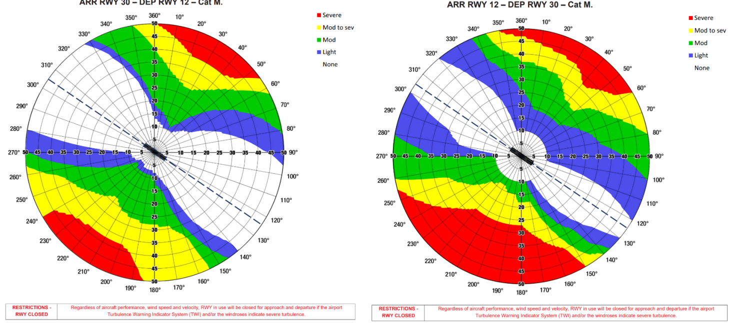
Live updated turbulence information can be found here
1.2.2 MSA
MSA is 4000' in 25 nm. radius
1.2.3 Approach procedures
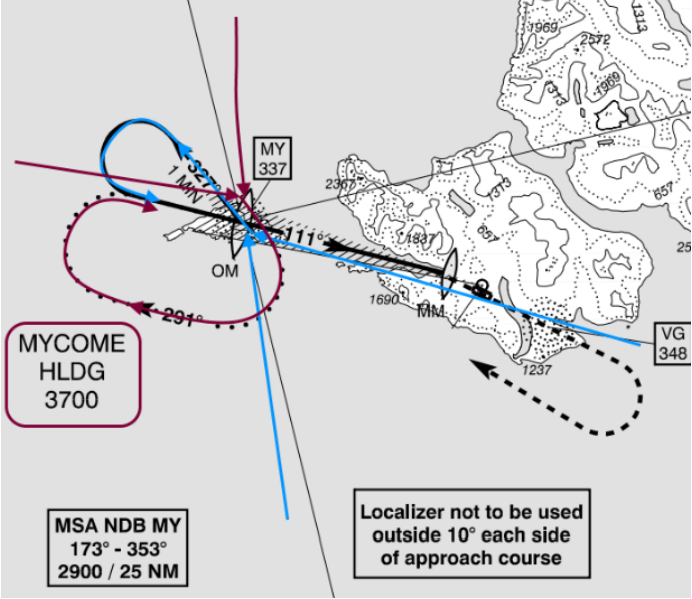
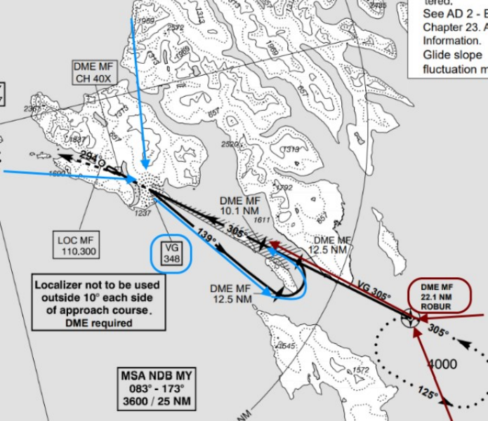
As AFIS you recommend the appropriate procedure, and recommend the descend, and asks them to Report Beacon outbound in the procedure/baseturn (VG or MY) and then Beacon inbound (MY) or on final (Rwy 30).
1.3 Other arrival procedures
1.3.1 RNP Approaches
EKVG has RNP-AR (Required Navigation Performance – Approval Required) procedures applicable to some airlines in order to perform approaches and SIDs. At this point this is limited to:
- A319 & A320 with Atlantic Airways
- A319 & A320 & A32N with SAS
Other airlines may get these on request only, and should be limited to Airbus & Embraer aircraft, as others may not have these capabilities.
In case of RNP-AR following procedures are applicable.
| Runway 12 | |||
| Direction | Point | Altitude | Procedure |
| East | ROBUR | 7000' | Full procedure RNP V or RNP W |
| South | SUDUR | ||
| West | MAGNI | ||
| North | |||
| Runway 30 | |||
| Direction | Point | Altitude | Procedure |
| East | ROBUR | 7000' | Straight in ILS V, RNP W, RNP V or RNP U |
| South | SUDUR | RNP W, RNP V or RNP U | |
| West | MAGNI | Full procedure ILS V, RNP W, RNP V or RNP U | |
| North | |||
See charts for ILS V, RNP V, RNP U and RNP W layout.
1.3.2 NDB Visual approach
NDB visual approaches is available on pilot request only during daylight hours. This approach
transitions to two available visual segments.
- Waterfall visual approach: Only for VFR & RNP-AR approved A/C (1.3.1)
- Standard visual segment: Available for everyone
1.4 Departure procedures
EKVG has established SIDs which are given as pr. BIRD instructions however appropriate SIDs should be assigned.
| Directrion | Runway 12 | Runway 30 | Initial climb | ||
| Other A/C | SID (RNP-AR) | SID (RNP-AR) | Other A/C | ||
| East | Visual Departure | ODEVA2P/2N | LUVEK2S/2T/2W | Visual departure | 7000' |
| South | RAKUP2P/2N | RAKUP2S/2T/2W | |||
| West | MY2P/2N | MY2S/2T/2W | |||
| North | |||||
1.4.1 Visual Departure
All aircraft which does not live up to 1.3.1 RNP-AR requirements must perform a VFR departure, and hence visibility must be more than 3KM, and no clouds below 3000’ AGL
If the pilot is aware of this, and wishes to bust the VFR minima, it is his discretion.
A visual departure is given by stating:
- After Departure climb visually, when clear of terrain, proceed direct to [Point]
1.4.2 SID-AR departures
For Airbus & other capable aircrafts, SID-AR are available.
Different ones are available, and must be used according to wind direction
| Wind direction | SID name depending on direction of departure. | |
| Runway 12 | Runway 30 | |
| 020 - 040 | ODEVA/RAKUP/MY 2S departures | ODEVA/RAKUP/MY 2P |
| 040 - 150 | RWY not in use | |
| 150 - 200 | ODEVA/RAKUP/MY 2T departures | |
| 160 - 200 | ODEVA/RAKUP/MY 2W departures | |
| 200 - 230 | ODEVA/RAKUP/MY 2N departures | |
| 230 - 260 | RWY not in use | |
| 260 - 020 | ODEVA/RAKUP/MY 2P departures | |
After departure, when aircrafts are reporting airborne they should be transferred to the appropriate controller (BIRD_E_CTR, BIRD_CTR or BICC_FSS)
BGSF | Kangarlussuaq
Local operating procedures for BGSF.
General
The largest airport in Greenland, Kangarlussuaq Airport (BGSF), also known as Sondrestrom, serves a critical role in Greenland air traffic. While the expansion of Nuuk International Airport (BGGH) has made that airport the main international and domestic hub of Greenland, BGSF still serves as a critical diversion point and cargo hub. BGSF is also still the only controlled airport in Greenland.
|
Runway |
RWY Dimensions (m) |
Heading |
|
09 |
2810x60 |
089 |
|
27 |
2810x60 |
269 |
List of ATS Positions
|
Coordination Name |
VATSIM Logon |
Radio Callsign |
Frequency |
|
Sondrestrom Tower (SFT) |
BGSF_TWR |
“Sondrestrom Tower" |
118.300 |
|
Sondrestrom Approach (SFA) |
BGSF_APP |
“Sondrestrom Approach" |
126.200 |
Login Priority
All positions may be opened at any time.
Sondrestrom TWR
Sondrestrom Tower (BGSF_TWR) provides clearance delivery, ground, and tower control.
Delivery
NOTE: Typically, the preferred runway configuration is RWY 09 for arrivals / RWY 27 for departures. See "Runway Configuration" below for more details.
Overview of SIDs
|
TERMINATING FIX |
RUNWAY |
|
|
09 |
27 |
|
|
BAVKO |
1A |
1B |
|
GILPO |
1A |
1B |
|
INPOD |
1A |
– |
|
ISTEC |
1A |
1B |
|
KEMOS |
1A |
1B |
|
WUTAN |
1A |
1B |
|
Initial Climb FL190 for Eastbound flights (TRK 000-179) FL180 for Westbound flights (TRK 180-359) (or RFL if lower) |
||
Clearance Procedure
All BGSF departures shall be given the latest weather (met report) with their IFR clearance. E.g.,
🎧 GRL418, ready to copy clearance and the weather?
🧑✈️ Ready to copy, GRL418.
🎧 GRL418, cleared to Keflavik via the WUTAN 1A departure, climb via SID FL190, Mach .80, squawk 3126.
🧑✈️ Cleared to Keflavik via the WUTAN 1A departure, climb via SID FL190, squawk 3126.
🎧 GRL418, readback correct. Kangarlussuaq met report at time 50, automatic, winds 060 degrees 9 knots, visibility 10 kilometers or more, no directional variation, clouds broken at 21000ft, temperature plus one, dewpoint minus four, QNH 1014.
🧑✈️ QNH 1014, GRL418.
🎧 GRL418, readback correct.
RWY 27 Departure Procedure (Non-RNAV)
This is necessary to avoid high terrain near the airport. 5300ft is the MSA (Minimum Safe Altitude) within 25 NM of BGSF.
The same initial climb applies as for the SIDs (FL190 for Eastbound departures / FL180 for Westbound, or RFL if lower.)
Ground
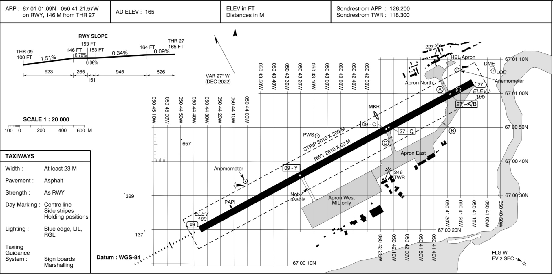
There are three main parking locations at BGSF:
- The North Apron is for scheduled passenger flights.
- The East Apron is for cargo and general aviation.
- The West Apron is for military operations.
Otherwise, BGSF has a fairly simple ground layout. The most important thing to note is that in the usual runway configuration (RWY 09 arrivals / RWY 27 departures), if an arrival requires full length for landing, it would likely vacate the runway from the same taxiways as departing aircraft would be holding short at. Controllers may consider instructing arrivals to make a 180 and backtrack to vacate, in order to avoid coming face-to-face with departing aircraft.
Tower
Runway Configuration
Due to high terrain near the airport, RWY 09 is the preferred arrival runway and RWY 27 is the preferred departure runway. Therefore, if the tailwind component for both runways is less than 10 KTS, TWR shall designate RWY 09 as the arrival runway and RWY 27 as the departure runway.
In this configuration, departures will depart into the arrival path. Typically this is not an issue due to BGSF’s low traffic levels, but TWR must coordinate with APP to ensure that large enough gaps are left in the arrival stream for aircraft to depart between arrivals.
When the tailwind component exceeds 10 KTS for either RWY 09 or RWY 27, TWR shall revise the runway configuration to depart & arrive on whichever runway has the strongest headwind component. The only exception is if conditions are IMC and/or if the ceiling is lower than 2200ft, in which case RWY 27 must be used for departure.
In periods of heavy traffic (assuming visibility is sufficient), TWR may also revise the runway configuration to use the same runway for departure/arrival, if it is expected that using opposite runways for departure and arrival would cause significant delays.
Sondre Stromfjord Control Zone (BGSF CTR)
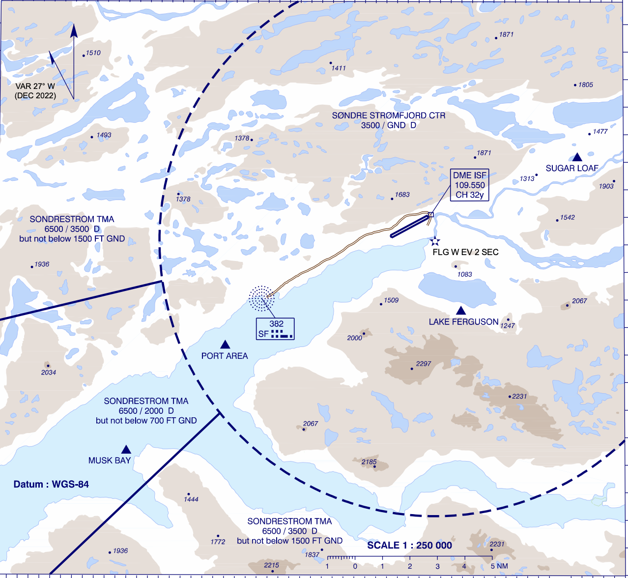
Note: the northeastern-most area of the BGSF CTR is cut off in the above image.
The Sondre Stromfjord Control Zone (BGSF CTR) surrounds BGSF from GND – 3500ft.
There are three visual reporting points which aircraft may follow while entering/exiting the CTR – Port Area, Musk Bay, and Sugar Loaf.
Due to surrounding high terrain, a left hand traffic pattern is preferred for RWY 27, and a right hand traffic pattern is preferred for RWY 09.
Missed Approaches
TWR shall instruct aircraft to follow the standard missed approach, and coordinate all missed approaches with APP prior to transferring to APP.
For aircraft unable the standard missed approach, TWR should instruct them to perform a visual climb and caution them of high terrain. The MSA within 25 NM of BGSF is 5300ft.
Sondrestrom APP
Sondrestrom Approach (BGSF_APP) provides an approach control service within the Sondrestrom TMA and CTA.
Sondrestrom TMA & CTA
The Sondrestrom TMA and CTA together make up the airspace controlled by Sondrestrom Approach.
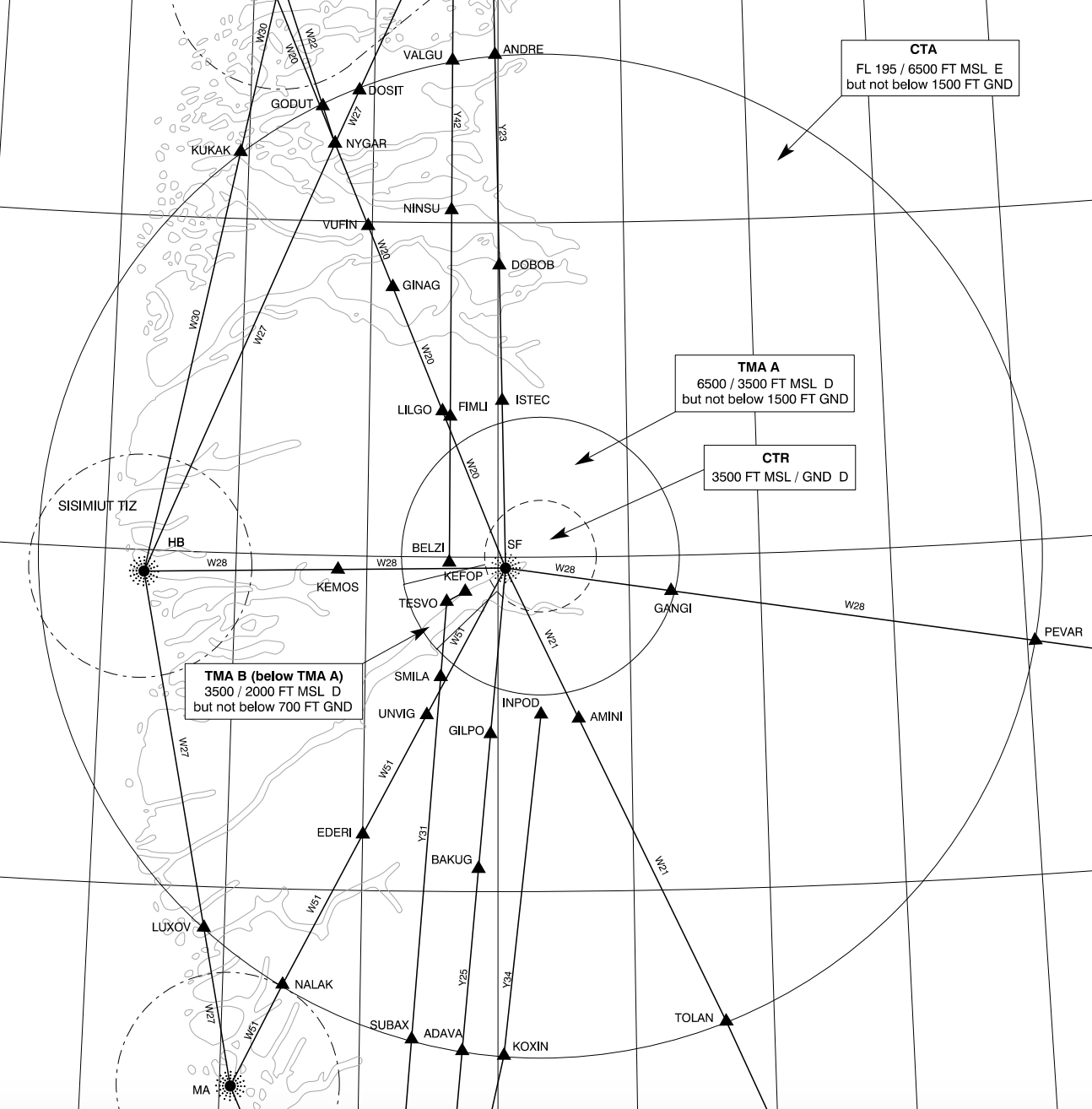
The CTA and TMA are arranged as three sections of cylindrical airspace.
- The CTA (6500ft – FL195) is the largest cylinder of airspace.
- TMA A (3500 – 6500ft), the main portion of the TMA, forms a smaller cylinder beneath the CTA.
- TMA B (2000 – 3500ft) is a small cylindrical segment, extending the TMA downwards to encompass the RWY 09 approach path. It directly underlies TMA A.
Arrivals
There are no STARs into BGSF. Aircraft generally join the instrument approach procedures directly from their flight plan route.
Runway 09
The RNP approach for RWY 09 is the preferred approach type. Aircraft should be cleared to either of the IAFs (DODIP or BELZI) and descended to the initial approach altitudes as published:
- DODIP: 5200ft
- BELZI: 4900ft
Missed Approach
TWR shall instruct aircraft to follow the standard missed approach. The standard missed approach varies between approaches:
- RNP: Climb runway track, passing 2500ft left turn direct SFT09, then direct KEFOP, climbing to 4000ft.
- LOC Z/Y: Climb on LOC course until the marker, then turn right track 103, passing 4000ft direct SF NDB, climbing to 4400ft.
- NDB Z/Y: At D2.5 ISF climb to 3000ft on track 097, then turn right direct SF NDB, climbing to 4400ft.
- RNP A/B (RWY 27): Climb on course 274, passing 3000ft direct KEFOP, climbing to 4000ft.
Strict adherence to the standard missed approaches is critical due to high terrain surrounding the airport.
TWR shall instruct aircraft unable the standard missed approach to perform a visual climb.
TWR shall coordinate all missed approaches with APP prior to transferring back to APP.
Non-Standard Approaches (RWY 09)
If aircraft are unable to accept the RNP approach, then alternative approaches should be offered in order of precision.
LOC Z/Y
There are two published localizer approaches – LOC Z (for category A and B aircraft) and LOC Y (for category C and D aircraft.) They are both teardrop procedures, starting from SF NDB and making a left turn inbound for the localizer.
As both procedures descend into the BGSF CTR, APP should coordinate with TWR to make them aware if the approaches are used.
NDB Z/Y
There are, similarly two NDB approaches – NDB Z (for category A and B) and NDB Y (for category C and D.) They are also teardrop procedures, except instead of using the localizer, aircraft fly a final approach course towards SF NDB and the runway.
As both procedures descend into the BGSF CTR, APP should coordinate with TWR to make them aware if the approaches are used.
Runway 27
While not officially published for RWY 27, there are two RNP approaches available which lead aircraft to RWY 27. (RNP A for categories A and B, and RNP B for categories C and D.)
Aircraft should be cleared to one of the three IAFs (RUMAQ, FICWE, or KEFOP) and descended to the initial approach altitudes as published:
- RUMAQ: 4000ft
- FICWE: 5000ft
- RIVOP: 4700ft
Alternatively, aircraft may perform a visual approach.
Circle-to-land is not permitted north of the aerodrome.
Departures
Aircraft shall follow either their SID, or the non-RNAV RWY 27 departure procedure of climbing on runway track, then when passing 5300ft, proceeding direct to join their flight planned route.
Strict adherence to the SID is required below the MSA (5300ft) due to high terrain. After passing the MSA, APP may issue a direct to the end of the SID, traffic permitting.
BGGH | Nuuk Int'l
Local operating procedures for BGGH.
Nuuk AFIS
A reminder that to log on as Nuuk AFIS (BGGH_I_TWR), you must have a T2 BIRD AFIS endorsement.
Delivery
Overview of SIDs
|
END FIX |
RWY 04 |
RWY 22 |
|
AMABI |
1A |
1B |
|
AMKOX |
1A |
1B |
|
EVULO |
1A |
1B |
|
NUKRI |
2A |
2B |
|
ASCOX |
1A |
1B |
|
SUBUD |
1A |
1B |
|
DODFO |
2A |
2B |
All SIDs require RNP 1 capability.
As per AFIS SOP, clearance shall be issued by BGGH_APP (If online), If not clearance will be issued by Nuuk Information or BIRD.
Standard initial climb for BGGH is FL290, but can be FL190 depending on the clearance issued by BIRD or NUUK.
A reminder that BGGH is a rare case of an AFIS aerodrome with an ATIS. Nuuk AFIS shall maintain the ATIS accordingly and shall check that all departing and arriving aircraft are in receipt of the ATIS.
Ground
Certain conditions apply to taxi & pushback for different aircraft. Reference the table below.
|
ACFT TYPE |
CONDITIONS |
STANDS (ranked by priority) |
PARKING ANGLE |
|
A338 |
Taxi in / push out |
A1 |
45° |
|
Boeing 757 (all variants) |
Taxi in / push out |
A1 |
45° |
|
Boeing 737 (all variants) |
Taxi in / push out |
A2, A3, A1 |
90° (45° on A1) |
|
A318, A319, A320, A321
A19N, A20N, A21N |
Taxi in / push out |
A2, A3, A1 |
90° (45° on A1) |
|
Q400 |
Taxi in / taxi out |
A2, A3, A1 |
45° |
|
Q200 |
Taxi in / taxi out |
A2-3-4A, B-5A&B, A1, B |
45° |
|
Larger private jets |
Taxi in / taxi out |
B1-2-3, A2, A1 |
Marshaller |
|
GA |
Taxi in / taxi out |
B1-2-3 |
Marshaller |
For pushback, Code D & E aircraft shall be pushed back to taxiway C for engine start, or holding point A if unable due to tailwind. With tailwind on taxiway A, aircraft may be towed to the RWY 04 threshold for startup.
During taxi, you can issue the following phrasiooligy "Passing 2000 or when workload permits, contact approach 121.300". Further on from this, you can issue the "no reported traffic" as per AFIS SOP.
On Runway / Airborne Traffic
Upon entering the runway, no instructions or clearances shall be issued. AFIS shall provide flight information service, per SOP.
Nuuk AFIS is a non-radar station. Procedural methods for traffic information & suggested separation should be used.
Approach Procedures
Aircraft will be handed to you when established on one of the procedures for each runway
| Runway 04 | Runway 22 | Runway unspecified |
| ILS Z | ILS Z | RNP A |
| ILS Y | ILS Y | RNP B |
| ILS X | ILS X | RNP C |
| LOC Z | LOC Z | |
| LOC Y | LOC Y | |
| LOC Z | LOC Z | |
| RNP Z | ||
| RNP Y |
Foreign/Local Separation
Nuuk currently operates an 8 OPS per hour rule, which will soon be increased to 15.
Departures on the same SID are separated with a minimum of 3 minutes separation.
Nuuk APP
A reminder that to log on as Nuuk AFIS (BGGH_APP), you must have a T2 BIRD AFIS endorsement.
Approach Procedures
BIRD or NUUK will hand over the aircraft to BGGH_APP when passing FL200 (Sometimes higher)
There are no STARs in BGGH. There are instrument approach procedures – the ILS Z shall be used for CAT A & B aircraft, and the ILS Y for CAT C & D aircraft.
Procedures are listed below:
| Runway 04 | Runway 22 | Runway unspecified |
| ILS Z | ILS Z | RNP A |
| ILS Y | ILS Y | RNP B |
| ILS X | ILS X | RNP C |
| LOC Z | LOC Z | |
| LOC Y | LOC Y | |
| LOC Z | LOC Z | |
| RNP Z | ||
| RNP Y |
There are no STARs into BGGH. There are instrument approach procedures – the ILS Z shall be used for CAT A & B aircraft, and the ILS Y for CAT C & D aircraft.
In the absence of radar and ATC, aircraft should be suggested to follow procedural separation methods (e.g., only 1 aircraft on final approach at a time.)
Foreign/Local Separation
Nuuk currently operates an 8 OPS per hour rule, which will soon be increased to 15.
Departures on the same SID are separated with a minimum of 3 minutes.
Departues
AFIS will instruct aircraft to contact APP when passing 2000ft or when workload permits.
As approach, you will instruct the pilot to report when reaching FL180, then hand over to BIRD or NUUK.
Preferred Practices
Local traffic preferences are as follows (these may be communicated to the pilots as "suggested" or "preferred" procedures, actions, etc.):
- Jets are advised to use holdings NUNBA or ERALA, to avoid wake turbulence and speed issues with
other traffic. - All other holdings are suggested at ABANO or GETDA, except missed approaches for CAT A & B aircraft initially climbing or taking up holding in CALRI before commencing new approach.
- After a missed approach, for extended holding, climb above the FIZ (8000 ft).
- For turboprops, RWY22 will be favoured for landing up to a tailwind component of 10 kts due to most traffic arriving from the north.
- Aircraft are not forced to accept a tailwind component landing, and may request otherwise. AFIS should endeavour to approve such requests, but may deny requests based on departing & arriving traffic flow, and pilots should expect delays.
- No takeoffs in the opposite direction of inbound traffic once landing traffic has passed IAF inbound.
Reykjavik ACC/OAC
Local operating procedures for Reykjavik ACC/OAC positions.
General
Full List of ATS Positions
|
Coordination Name |
VATSIM Logon |
Radio Callsign |
Frequency |
|
South 1 (S1) |
BIRD_S1_CTR |
Reykjavik Control |
119.700 |
|
South 2 (S2) |
BIRD_S2_CTR |
125.700 |
|
|
South 3 (S3) |
BIRD_S3_CTR |
128.600 |
|
|
East 1 (E1) |
BIRD_E1_CTR |
126.750 |
|
|
East 2 (E2) |
BIRD_E2_CTR |
132.200 |
|
|
East 3 (E3) |
BIRD_E3_CTR |
128.800 |
|
|
West 1 (W1) |
BIRD_W1_CTR |
124.400 |
|
|
West 2 (W2) |
BIRD_W2_CTR |
127.500 |
|
|
West 3 (W3) |
BIRD_W3_CTR |
128.200 |
|
|
North 1 (N1) (EVENT ONLY) |
BIRD_N1_CTR |
133.100 |
|
|
Radio 1 (CC1) |
BICC_1_FSS |
Iceland Radio |
127.850 |
|
Radio 2 (CC2) |
BICC_2_FSS |
126.550 |
|
|
Radio 3 (CC3) (EVENT ONLY) |
BICC_3_FSS |
129.625 |
Login Priority
Reykjavik Control (BIRD_**_CTR)
South 1 (BIRD_S1_CTR) may be opened at any time. All other BIRD positions may only be opened after South 1 has been opened (except if South 2 and South 3 are being opened at the same time.)
Iceland Radio (BICC_*_FSS)
Radio 1 (BICC_1_FSS) may be opened at any time. All other BICC positions may only be opened after Radio 1 has been opened. See the Iceland Radio page for more information.
Sectorization

The Reykjavik CTA is divided into four lateral sectors: North, South, East, and West.
Bandboxing
The South sector positions (S1 / S2 / S3) bandbox the East & West sectors when no controllers are online for those sectors.
Dynamic Vertical Splits
Each sector may be dynamically split up vertically to three times to increase traffic capacity, following these rules:
- When two sector splits numbered 1 & 2 are online, they shall split the sector at FL345 (split 1 is lower, 2 is higher.)
- When two sector splits numbered 1 & 3 are online, they shall split the sector at FL355.
- When two sector splits numbered 2 & 3 are online, they shall split the sector at FL365.
- When three sector splits (1, 2, and 3) are online, sector no. 1 covers up to FL345, sector no. 2 from FL345-FL365, and sector no. 3 from FL365+.
Bandboxed Splits
If there are multiple South sectors online, but no East or West sectors are online, the South positions shall split the South, East, and West sectors at the same level.
- For example, if South 1 and South 3 are both online, then they would bandbox the South, East, and West sectors and split them all at FL355.
- However, if East 1 were then to come online, they would take over the entire East sector top to bottom, and South 1/South 3 would continue to bandbox the South and West sectors, splitting at FL355.
Top-Down
Whichever Reykjavik Control position covers the lowest vertical levels also covers all local (aerodrome, approach, etc.) positions in that sector top-down. For specific aerodrome top-down coverage for each respective sector, see their individual pages.
Oceanic Procedures
All aircraft in Reykjavik OCA must follow oceanic procedures. See the Oceanic Area Control SOP for details.
South Sector
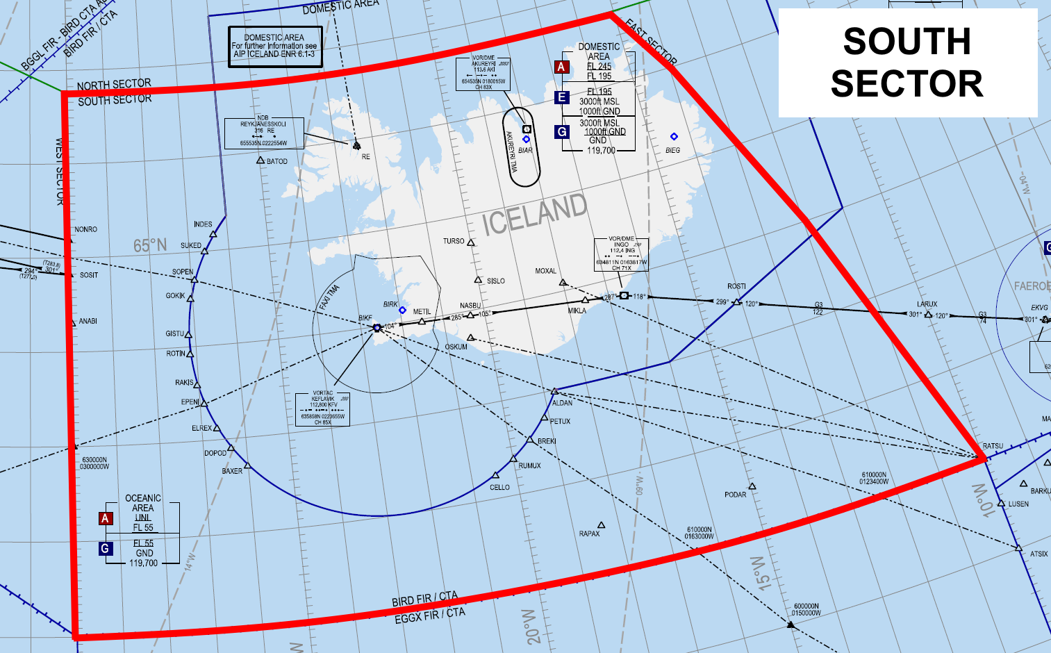
The South sector directly overlies Iceland, containing the majority of the Icelandic Domestic Area. It is bordered by the Shanwick OCA to the South.
Airspace Classification
Excluding TMAs, CTRs, and ATZs, the South sector is classified as:
- Class A from:
- FL195+ within the lateral boundaries of the Domestic Area.
- FL55+ elsewhere.
- Class E within the boundaries of the Domestic Area, from 3000ft — FL195.
- Class G from GND — 3000ft within the lateral boundaries of the Domestic Area, and GND — FL55 elsewhere.
List of ATS Positions
|
South 1 (S1) |
BIRD_S1_CTR |
Reykjavik Control |
119.700 |
|
South 2 (S2) |
BIRD_S2_CTR |
125.700 |
|
|
South 3 (S3) |
BIRD_S3_CTR |
128.600 |
|
|
Radio 1 RCL ONLY |
BICC_1_FSS |
Iceland Radio |
127.850 |
|
Radio 2 RCL ONLY |
BICC_2_FSS |
126.550 |
Underlying Aerodromes
Controlled
BIKF
BIRK
BIAR
AFIS
BIBD
BIEG*
BIGJ
BIGR
BIHU
BIHN
BIIS
BIKR
BIVM*
BIVO
BITN
*AFIS aerodrome which has an associated ATZ. All other AFIS aerodromes in Iceland have no associated ATZ.
Uncontrolled
Various small landing strips; see Iceland AIP.
Delegated Airspace
NIL.
Oceanic Entry (RCL)
Airborne aircraft entering the South sector from domestic airspace (or from oceanic airspace with offline ATC) shall transmit their RCL message to the following positions, in order of priority:
- Radio 2 (BICC_2_FSS)
- Radio 1 (BICC_1_FSS)
- The South sector whose level the aircraft will be entering.
- E.g., if South 1 & South 3 are online, splitting the South sector at FL355, an inbound aircraft at FL365 would transmit their RCL message to South 3.
Procedures
To/From Faxi TMA (BIKF & BIRK)
Departures and arrivals into BIKF/BIRK shall follow standard routes defined in the Iceland AIP, ENR 1.8.4.1.3.7.
The departure routings may be found in LOPs for BIKF and BIRK. The arrival routings may be summarized as follows:
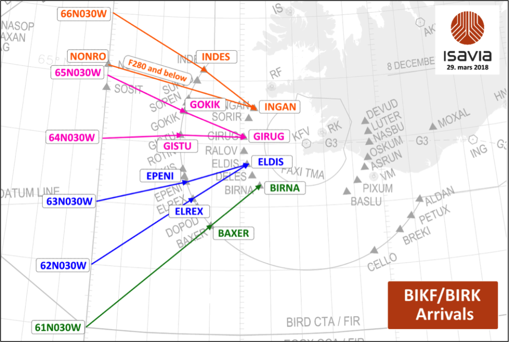
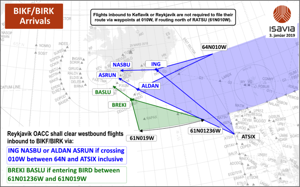
If aircraft have not filed via these standard arrival routings, then Reykjavik Control shall amend their routing appropriately when responding to their RCL message.
Reykjavik Control clears arrivals onto the STAR and descends the aircraft via STAR to FL100. Reykjavik Control transfers communications to Keflavik Approach 60 NM from KFV. Such arrivals are considered fully released.
Departures are transferred to Reykjavik Control at the TMA boundary (note: not at the 60 NM ring).
To/From Akureyri TMA (BIAR)
Reykjavik Control clears arrivals onto the STAR and descends the aircraft to 7000ft. Reykjavik transfers communications upon the aircraft commencing the STAR. Such arrivals are released for descent.
To/From Icelandic AFIS Aerodromes
If the local AFIS unit is offline, the lowest South sector provides top-down AFIS.
See the SOP ATS Surveillance page for information regarding descent out of controlled airspace over Iceland.
Some AFIS aerodromes (e.g., BIIS) only permit VFR traffic – see the Icelandic AFIS quick reference page. In these instances, Reykjavik ACC may only issue IFR clearance once the aircraft is airborne, or issue a conditional IFR clearance that is only valid upon entering controlled airspace (or commencing a published SID, such as at BIIS.)
East Sector
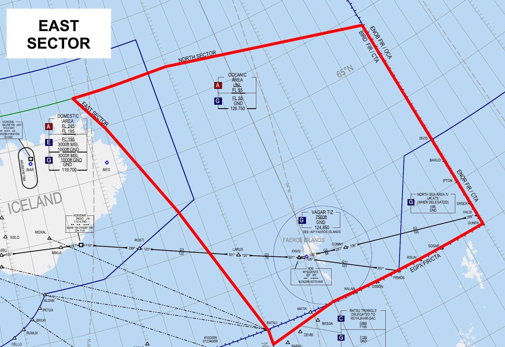
The East sector overlies the Faroe Islands, and contains a small portion of the Icelandic Domestic Area.
It is bordered by Scottish FIR (EGPX), Stavanger ACC (ENSV) of Polaris FIR, and Bodo OFIR (Oceanic FIR). It also shares a small border (on the Westernmost side of the RATSU Triangle) with Shanwick OCA (EGGX).
Airspace Classification
Excluding the Vagar FIZ, the East sector is:
- Class A from FL195+ within the lateral boundaries of the Domestic Area, and FL55+ elsewhere.
- Class E from 3000ft – FL195 within the boundaries of the Domestic Area.
- Class G from GND – 3000ft within the lateral boundaries of the Domestic Area, and GND – FL55 elsewhere.
List of ATS Positions
|
East 1 (E1) |
BIRD_E1_CTR |
Reykjavik Control |
126.750 |
|
East 2 (E2) |
BIRD_E2_CTR |
132.200 |
|
|
East 3 (E3) |
BIRD_E3_CTR |
128.800 |
|
|
South 1 (S1) Only if no East sector online |
BIRD_S1_CTR |
119.700 |
|
|
South 2 (S2) Only if no East sector online |
BIRD_S2_CTR |
125.700 |
|
|
South 3 (S3) Only if no East sector online |
BIRD_S3_CTR |
128.600 |
|
|
Radio 1 (CC1) RCL ONLY |
BICC_1_FSS |
Iceland Radio |
127.850 |
Underlying Aerodromes
AFIS
EKVG
Delegated Airspace
RATSU Triangle
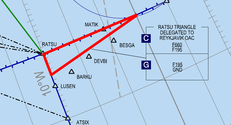
The RATSU Triangle (GND – FL660) is located at the southwest corner of the East sector. It is delegated from Scottish (EGPX) FIR to Reykjavik Control. It is classified:
- Class C from FL195 – FL660
- Class G from GND – FL195
See BIRD-EGPX LOA for more information.
North Sea Area IV
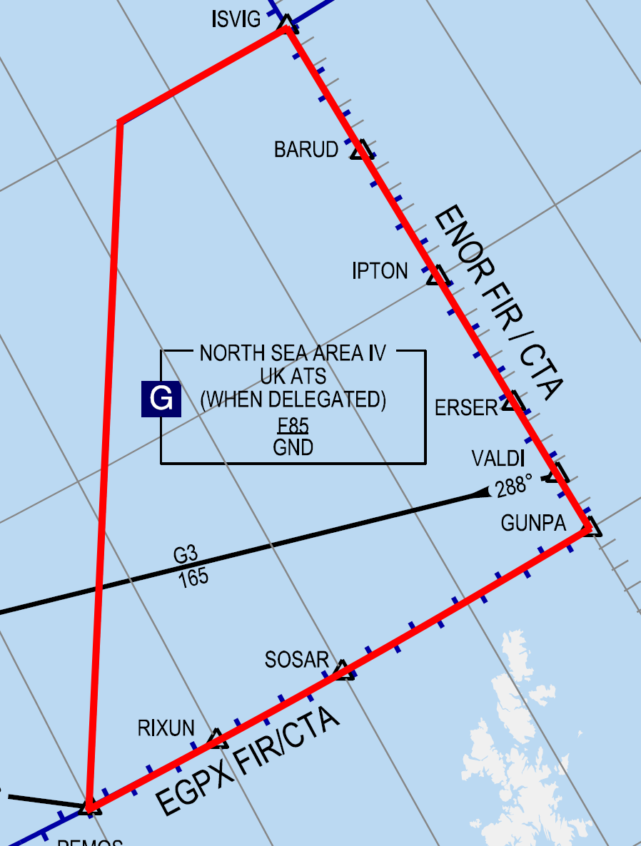
North Sea Area IV (GND – FL85), or simply "Area IV," is located at the southeast corner of the East sector. It is delegated from Reykjavik Control to Sumburgh Radar (Prestwick ACC) in Scotland. It is Class G. See BIRD-EGPX LOA for more information.
Oceanic Entry (RCL)
Airborne aircraft entering the East sector from domestic airspace (or from oceanic airspace with offline ATC) shall transmit their RCL message to the following positions, in order of priority:
- Radio 1 (BICC_1_FSS)
- The East sector whose level the aircraft will be entering (or South sector bandboxing East, if no East sectors are online.)
- E.g., if East 1 & East 3 are online, splitting the East sector at FL355, an inbound aircraft at FL365 would receive OCL from East 3.
- E.g., if East 1 & East 3 are online, splitting the East sector at FL355, an inbound aircraft at FL365 would receive OCL from East 3.
Procedures
To/From EKVG
If the local AFIS unit is offline, the lowest East sector provides top-down AFIS for EKVG.
For arrivals, Reykjavik Control shall descend aircraft to the Transition Level (TL) for EKVG, then clear the aircraft to descend below controlled airspace. Reykjavik Control shall not clear aircraft onto any instrument procedures, as the procedures are entirely within uncontrolled airspace.
Reykjavik Control may ask aircraft what their intended approach is, and share this information with Vagar AFIS as appropriate.
For departures, Reykjavik Control shall clear aircraft onto the SIDs, as they enter controlled airspace.
Neighboring Sectors Without LOAs
In lieu of official LOAs regarding the sectors below, note the following information.
NOTE! The information below is provided for reference only, and is not a substitute for proper coordination with these sectors in the absence of an LOA.
EGGX (Shanwick)
NAT_FSS is the bandbox position for Gander & Shanwick OCAs.
- When transferring aircraft to NAT_FSS that are entering Shanwick OCA, the appropriate radio callsign is “Shanwick Radio” (i.e., “contact Shanwick Radio on…”)
In real life, Reykjavik Control passes to Shanwick Radio (by coordination) a squawk code for all aircraft entering Reykjavik OCA from Shanwick OCA. The intention is that the aircraft are squawking the Reykjavik-assigned code by the time they enter the Reykjavik OCA.
As this is not formally defined in an LOA, not all Shanwick/NAT controllers will be aware of this procedure. Therefore, this procedure should only be adopted if mutually coordinated/agreed by both Shanwick & Reykjavik controllers.
West Sector
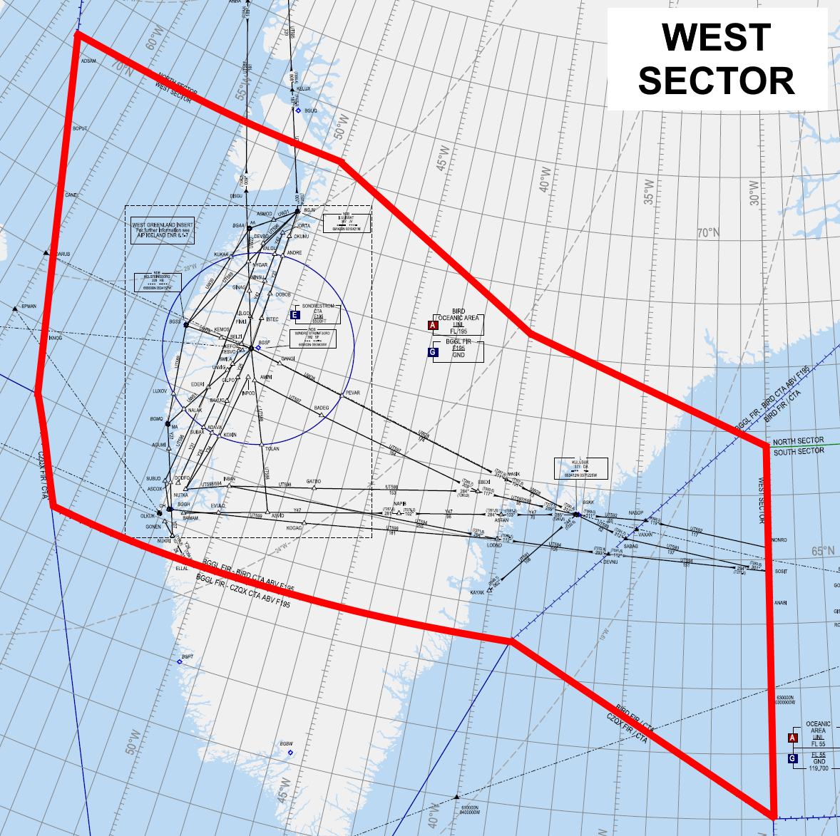
The West sector overlies central Greenland, including Kangarlussuaq airport (BGSF), the largest commercial airport in Greenland. It is surrounded by Gander OCA to the South, as well as Gander domestic FIR and Edmonton FIR to the East.
Airspace Classification
The West sector is classified as:
- Class A from:
- FL55+ within BIRD FIR.
- FL195+ within BGGL FIR (see Delegated Airspace below.)
- Class G from GND — FL55 within BIRD FIR, and GND – FL195 within BGGL FIR.
Within BGGL FIR, flight information service is provided by Nuuk Information (BGGL_FSS.) Reykjavik Control does not cover Nuuk Information top-down, and therefore, no West sector position provides FIS within BGGL FIR below FL195.
Iceland Radio positions may, at their discretion, provide top-down for Nuuk Information. See the Iceland Radio page for more information.
List of ATS Positions
|
West 1 (E1) |
BIRD_W1_CTR |
Reykjavik Control |
124.400 |
|
West 2 (E2) |
BIRD_W2_CTR |
127.500 |
|
|
West 3 (E3) |
BIRD_W3_CTR |
128.200 |
|
|
South 1 (S1) Only if no West sector online |
BIRD_S1_CTR |
119.700 |
|
|
South 2 (S2) Only if no West sector online |
BIRD_S2_CTR |
125.700 |
|
|
South 3 (S3) Only if no West sector online |
BIRD_S3_CTR |
128.600 |
|
|
Radio 1 Only if no BIRD online |
BICC_1_FSS |
Iceland Radio |
127.850 |
|
Radio 2 OCL ONLY |
BICC_2_FSS |
126.550 |
Underlying Aerodromes
Controlled
BGSF
Reykjavik Control positions do not provide top-down AFIS to any Greenlandic aerodromes underlying the West sector. They may, however, issue IFR/oceanic clearance to departures from such aerodromes – see below.
Delegated Airspace
A significant portion of the West sector consists of airspace delegated from Greenland (Nuuk FIR | BGGL) to Iceland (Reykjavik ACC) from FL195+. Reykjavik ACC provides enroute ATC service in this airspace, which is (like the rest of the OCA) classified as Class A.
The diagram below indicates which portions of the North sector are delegated from BGGL FIR (i.e., controlled from FL195+), and which portions are part of BIRD FIR (i.e., controlled from FL55+.)
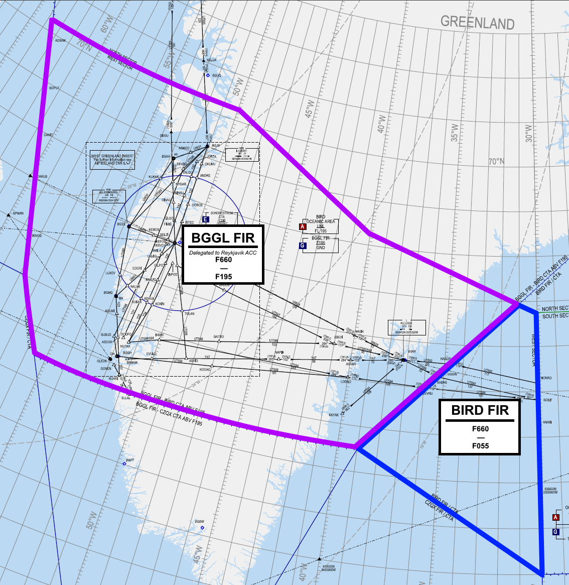
Oceanic Entry (RCL)
Airborne aircraft entering the South sector from domestic airspace (or from oceanic airspace with offline ATC) shall transmit their RCL message to the following positions, in order of priority:
- Radio 1 (BICC_1_FSS)
- The West sector whose level the aircraft will be entering.
- E.g., if West 1 & West 3 are online, splitting the West sector at FL355, an inbound aircraft at FL365 would receive OCL from West 3.
- If no West sectors are online, the South sector (bandboxing West) whose level the aircraft will be entering.
Procedures
To/From BGSF
Reykjavik Control provides top-down service in Sondrestrom CTA & TMA (and BGSF CTR/aerodrome) when no local BGSF positions are online.
All aircraft to BGSF are to be initially descended to FL200, to avoid descending below controlled airspace. Upon passing the lateral boundaries of Sondrestrom CTA, they may be transferred to Sondrestrom Approach (BGSF_APP) for further descent.
To/From Greenland AFIS Aerodromes
Reykjavik Control does not provide FIS in Nuuk FIR, or top-down AFIS for any Greenlandic AFIS aerodromes.
Reykjavik ACC does, however, relay (via local AFIS) IFR and oceanic clearances to aircraft departing Greenlandic (BG**) AFIS aerodromes beneath the North and West sectors. While this is handled by Iceland Radio when online, when Iceland Radio is offline, the lowest West sector shall perform this responsibility for the AFIS aerodromes beneath the West sector.
- IFR clearances are required for aircraft climbing above FL195 (i.e., into the CTA.)
- Oceanic clearances are required for aircraft climbing above FL285 and/or leaving BGGL FIR.
- Clearance is relayed via local AFIS if online. If not, aircraft shall contact BIRD directly for the clearance request, and after issuing the clearance, BIRD shall instruct them afterward to return to UNICOM until passing FL195.
All arrivals to Greenlandic aerodromes should be cleared to descend below controlled airspace prior to FL195. They may then be instructed “frequency change approved.”
Neighboring Sectors Without LOAs
In lieu of official LOAs regarding the sectors below, note the following information.
NOTE! The information below is provided for reference only, and is not a substitute for proper coordination with these sectors in the absence of an LOA.
CZQO/CZQX (Gander Oceanic & Domestic)
The domestic & oceanic control positions of Gander ACC/OACC are differentiated by their logon callsign, as follows:
- CZQO_CTR is the Gander Oceanic position, responsible for Gander OCA. Its callsign is “Gander Radio.”
- CZQO_DEL is the Gander Oceanic clearance delivery position.
- CZQX_CTR is the Gander Domestic position, responsible for Gander Domestic FIR. Its callsign is “Gander Center.”
- NAT_FSS is the bandbox position for Gander & Shanwick OCAs.
- When transferring aircraft to NAT_FSS that are entering Gander OCA, the radio callsign is “Gander Radio” (e.g., “contact Gander Radio on…”)
The Gander Oceanic Transition Area (GOTA) (FL290-UNL) is an area of airspace within Gander OCA that is delegated to Gander Domestic.

When Gander Radio/NAT_FSS is online, but Gander Center (domestic) is offline, then Gander Radio/NAT_FSS provides ATC service in GOTA (as well as below it).
When Gander Center is online, but Gander Radio/NAT_FSS is offline, then Gander Center provides ATC service in (but not below) GOTA.
When both Gander Radio/NAT_FSS and Gander Center (domestic) are online, then:
- Gander Center provides domestic ATC service in GOTA (FL290+).
- Gander Radio provides oceanic ATC service below GOTA (FL290-).
If there are no Gander positions online, Moncton Center (CZQM_CTR) may bandbox Gander FIR, including GOTA but not including the Gander OCA.
Iceland Radio (North Sector)
UPDATE: Effective 1 March 2024, Iceland Radio no longer requires a separate endorsement to control. All Iceland-familiarized C1 controllers are allowed to staff Iceland Radio.
The position of "Iceland Radio" serves a unique function within the VATSIM Reykjavik CTA, in relation to oceanic clearances and ATC service in the North sector.
List of ATS Positions
|
Radio 1 |
BICC_1_FSS |
Iceland Radio |
127.850 |
|
Radio 2 |
BICC_2_FSS |
126.550 |
|
|
Radio 3 EVENT ONLY |
BICC_3_FSS |
129.625 |
Introduction to Iceland Radio
In real life, radio operators at Gufunes Communication Centre in Reykjavik, using the callsign "Iceland Radio," relay communications from Reykjavik ACC/OAC to aircraft entering, or within, the Reykjavik CTA.
Since the abolishment of oceanic clearances in the BIRD OCA, Iceland Radio operators primarily relay Reykjavik ACC/OAC instructions & clearances to aircraft in the North sector. Iceland Radio also handles RCL messages for aircraft entering BIRD OCA, who are not CPDLC equipped.
For VATSIM purposes, we combine the role of the controller at Reykjavik ACC (who issues the clearances and instructions), and the role of the Gufunes radio operator (who relays them to the aircraft), into one.
North Sector
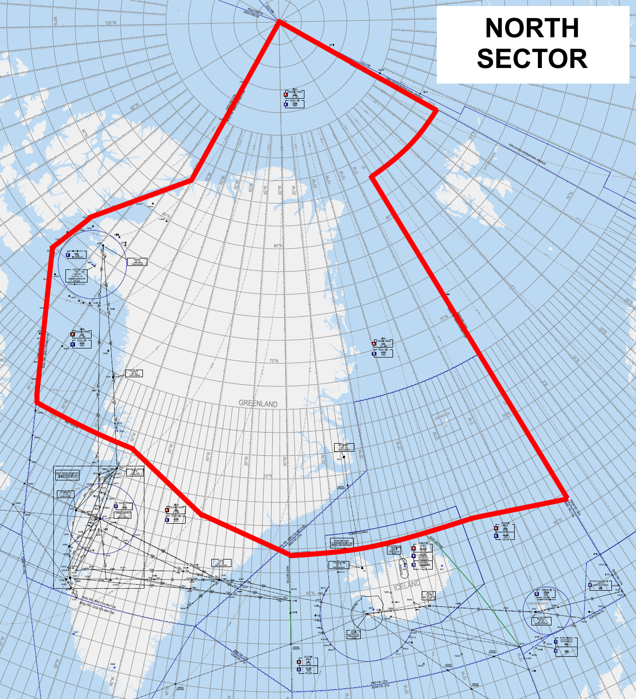
The North sector of Reykjavik OACC overlies northern Greenland and a large portion of the Arctic Sea. It is surrounded by Edmonton FIR to the West, and Bodo oceanic FIR to the East. It is also “bordered” by Murmansk FIR to the East, with a slight gap of uncontrolled (internationally disputed) airspace in between.
Airspace Classification
The North sector is classified as:
- Class A from:
- FL55+ within BIRD FIR.
- FL195+ within BGGL FIR (see Delegated Airspace below.)
- Class G from GND — FL55 within BIRD FIR, and GND – FL195 within BGGL FIR.
In BGGL FIR below FL195, flight information service is provided by Nuuk Information (BGGL_FSS), which is a separate position to Iceland Radio.
However, controllers staffing Iceland Radio may, at their discretion (workload permitting), choose to cover Nuuk Information's responsibilities top-down.
Underlying Aerodromes
NIL
If Iceland Radio chooses to cover Nuuk Information top-down, then Iceland Radio shall also provide top-down ATC for BGSF and top-down AFIS for other Greenlandic (BG**) aerodromes.
Delegated Airspace
A significant portion of the North sector consists of airspace delegated from Greenland (Nuuk FIR | BGGL) to Iceland (Reykjavik ACC) from FL195+. Reykjavik ACC provides enroute ATC service in this airspace, which is (like the rest of the OCA) classified as Class A.
The diagram below indicates which portions of the North sector are delegated from BGGL FIR (i.e., controlled from FL195+), and which portions are part of BIRD FIR (i.e., controlled from FL55+.)

Responsibilities and Procedures
Solo Operations
Radio 1 (BICC_1_FSS) shall always be the first Iceland Radio position to be opened. In isolation (i.e., with no other BICC positions online), Radio 1 shall perform the following responsibilities:
- An ADS-B based ATC service to aircraft in the North sector.
- With developments in ADS-B satellite coverage, the North sector is now fully covered by satellite ADS-B, and normal ATS surveillance procedures apply (procedural control is no longer required.)
- Processing & responding to RCL messages for airborne aircraft entering the Reykjavik OCA (all sectors, not just North.)
- Issuing IFR clearances to aircraft departing Greenlandic (BG**) AFIS aerodromes (throughout all of Greenland, not just the aerodromes underlying the North sector.)
- Clearance is relayed via local AFIS if online. If local AFIS is offline, aircraft shall contact Radio 1 directly for clearance. After issuing clearance, BICC shall instruct the aircraft to return to UNICOM until entering controlled airspace.
As described earlier, Radio 1 may also optionally (workload permitting) choose to cover the responsibilities of Nuuk Information (BGGL_FSS) top-down, including top-down ATC/AFIS for Greenlandic (BG**) aerodromes.
Split Operations
During heavy traffic situations, or events like CTP, it may be desirable to split the responsibilities of Iceland Radio across multiple positions/controllers.
Under routine circumstances, a two-way split is possible, between Radio 1 (BICC_1_FSS) and Radio 2 (BICC_2_FSS.)
Under such a split, Radio 1 (BICC_1_FSS) provides the following services:
- Processing & responding to RCL messages for aircraft entering the East and West sectors.
- IFR/oceanic clearance to aircraft departing Greenlandic AFIS aerodromes.
Radio 2 (BICC_2_FSS) provides:
- Processing & responding to RCL messages for aircraft entering the North and South sectors.
- ATC service to aircraft in the North sector.
(It is assumed that if the workload is heavy enough that two BICC positions are required, neither BICC position will have the capacity to also cover the responsibilities of Nuuk Information.)
During events, an additional Iceland Radio position/frequency, Radio 3 (BICC_3_FSS), may also be opened. Radio 3 is an “overflow” position with responsibilities assigned on an ad-hoc basis. It shall not be opened during normal operations.
Phraseology
Even though "Iceland Radio" is the callsign used by all the above BICC positions, all clearances and instructions should be given to pilots prefaced by the phrase “Reykjavik Control clears you…”
For example, for an amended route clearance issued in response to an RCL message:
🎧 AAL501, amended route clearance, Reykjavik Control clears you after ING direct NASBU.
This reflects the fact that in real life, Iceland Radio relays clearances & instructions from Reykjavik ACC/OAC ("Reykjavik Control.")
Minor AFIS Aerodromes
Information for minor Icelandic and Greenlandic AFIS aerodromes.
Icelandic AFIS Aerodromes (BI**)
As of 20th March 2024, all departing aircraft from a aifs airfield will receive a standard clearance but you are still required to receive the clearance from BIRD.
NOTE: All Icelandic AFIS aerodromes require a Tier 2 endorsement.
General Reminders
- The transition altitude for Iceland is 7000ft.
- IFR and oceanic clearance shall be obtained from the lowest BIRD South sector (usually BIRD_S1_CTR.)
- Only some aerodromes have ATZs. For all others, the AFIS unit is responsible for aircraft "in the vicinity of" the aerodrome (i.e., within, joining, or leaving the traffic circuit.)
BIBD | Bildudalur
Only VFR permitted.
- AFIS: Bildudalur Information (BIBD_I_TWR | 119.100)
- Runways: 04 / 22
- Published Approaches: RNP A / Cloud break via SB NDB
BIEG | Egilsstadir
- AFIS: Egilsstadir Information (BIEG_I_TWR | 118.800)
- ATZ: GND — 3000ft
- Runways: 03 / 21
- Traffic Circuit: Right-hand for RWY 21
- Approach Types:
- RWY 03: ILS, LOC, RNP, NDB
- RWY 21: RNP, NDB
BIGJ | Gjögur
- AFIS: Gjögur Information (BIGJ_I_TWR | 118.600)
- ATZ: None
- Runways: 04 / 22
- Published Approaches: RNP A, NDB A
BIGR | Grimsey
- AFIS: Grimsey Information (BIGR_I_TWR | 118.100)
- Runways: 04 / 22
- Published Approaches: RNP for RWY 35
BIHU | Husavik
- AFIS: Husavik Information (BIHU_I_TWR | 119.200)
- Runways: 02 / 20
- Published Approaches: RNP, NDB for RWY 02
BIHN | Hornafjordur
- AFIS: Hornafjordur Information (BIHN_I_TWR | 119.100)
- Runways: 18 / 31
- Traffic Circuit: Right-hand for RWY 18
- Published Approaches:
- RWY 18: RNP
- RWY 36: RNP, NDB
BIIS | Isafjordur
Only VFR permitted.
- AFIS: Isafjordur Information (BIIS_I_TWR | 118.800)
- Runways: 08 / 26
- Published Approaches: RNP (C/D), NDB C
- Aircraft may be cleared on the published approaches to descend out of controlled airspace. Once VFR, they should report their cancellation of IFR to Isafjordur Information.
BIKR (Saudarkrokur)
- AFIS: Saudarkrokur Information (BIKR_I_TWR | 119.100)
- Runways: 18 / 36
- Published Approaches: RNP for RWY 36
BIVM (Vestmannaeyjar)
- AFIS: Vestmannaeyjar Information (BIVM_I_TWR | 118.500)
- ATZ: GND – 3000ft
- Runways: 03 / 21, 12 / 30
- Traffic Circuit: Right-hand for RWYs 12 & 21
- Approach Types:
- RWY 03: RN
- RWY 21: RNP, NDB
- RWY 30: NDB RWY 30
- Cloud break via VM NDB
BIVO (Vopnafjordur)
- AFIS: Vopnafjordur Information (BIVO_I_TWR | 118.100) FF
- Runways: 04 / 22
- Published Approaches: RNP RWY 04
BITN (Thorshofn)
- AFIS: Thorshofn Information (BITN_I_TWR | 118.100)
- Runways: 01 / 19
- Published Approaches:
- RWY 01: RNP
- RWY 19: RNP, NDB
Greenlandic AFIS Aerodromes (BG**) except BGGH
NOTE: All Greenlandic AFIS aerodromes require a T2 BIRD AFIS endorsement.
Update: With the expansion of Nuuk airport (BGGH), its procedures have been moved to a separate page: Nuuk AFIS
General Reminders
- The transition altitude in Greenland varies between aerodromes.
-
For Greenlandic aerodromes, clearance shall first be obtained from Iceland Radio (BICC_1_FSS.) If Iceland Radio is not online, then:
- For aerodromes underlying the North sector or Gander (CZQO) OCA:
- Aircraft should be instructed to depart at their own discretion.
- For aerodromes underlying the West sector:
- Request clearance from the lowest BIRD West sector online (usually BIRD_W1_CTR), or the lowest South sector if no West sectors are online.
- For aerodromes underlying the North sector or Gander (CZQO) OCA:
BGJN | Ilulissat
- AFIS: Ilulissat AFIS (BGJN_I_TWR | 119.100)
- FIZ: GND – 6000ft
- Transition Alt: 6000ft
- Clearance From: Radio 1 (BICC_1_FSS), or lowest West sector, or lowest South sector
- Runways: 07 / 25
- Published Approaches:
- RWY 07: NDB/DME, NDB, NDB H
- RWY 25: NDB, NDB/DME
BGKK | Kulusuk
- AFIS: Kulusuk AFIS (BGKK_I_TWR | 118.100)
- FIZ: GND – 5000ft
- Transition Alt: 7000ft
- Clearance From: Radio 1 (BICC_1_FSS), or lowest West sector, or lowest South sector
- Runways: 11 / 29
- Published Approaches:
- RWY 11: RNAV, NDB
- RWY unspecified: RNAV Circle to land
BGMQ | Maniitsoq
- AFIS: Maniitsoq AFIS (BGMQ_I_TWR | 118.500)
- FIZ: GND – 5000ft
- Transition Alt: 9000ft
- Clearance From: Radio 1 (BICC_1_FSS), or Gander Radio (CZQO_FSS), or NAT bandbox (NAT_FSS)
- Runways: 16 / 34
- Published Approaches: NDB/DME for RWY 34
BGBW (Narsarsuaq)
- AFIS: Narsarsuaq 119.100
- FIZ: GND – FL100
- Transition Alt: 9000ft
- Clearance From: Radio 1 (BICC_1_FSS), or Gander Radio (CZQO_FSS), or NAT bandbox (NAT_FSS)
- Runways: 06 / 24
- Published Approaches: RNAV Z/Y for RWY 6 RNAV, NDB/DME, NDB Circle to land
BGCO (Constable Pynt)
- AFIS: Constable Pynt AFIS (BGCO_I_TWR | 118.100)
- FIZ: GND – FL70
- Transition Alt: 6000ft
- Clearance From: Radio 1 (BICC_1_FSS)
- Runways: 18 / 36
- Traffic Circuit: Right-hand for RWY 36
- Published Approaches: NDB A/B Circle to land
BGPT (Paamiut)
- AFIS: Paamiut (BGPT_I_TWR | 118.100)
- FIZ: GND – 6000ft
- Transition Alt: 6000ft
- Clearance From: Radio 1 (BICC_1_FSS)
- Runways: 17 / 35
- Published Approaches:
- RWY 17: RNAV
- RWY unspecified: RNAV Circle to land
BGQQ (Qaanaaq)
- AFIS: Qaanaaq AFIS (BGQQ_I_TWR | 118.100)
- FIZ: GND – FL70
- Transition Alt: 6500ft
- Clearance From: Radio 1 (BICC_1_FSS)
- Runways: 17 / 35
- Published Approaches:
- RWY 35: RNAV, NDB, NDB/DME, RWY 35
- RWY unspecified: RNAV A/B Circle to land
BGSS (Sisimiut)
- AFIS: Sisimiut AFIS (BGSS_I_TWR | 118.100)
- FIZ: GND – 6500ft
- Transition Alt: 8000ft
- Clearance From: Radio 1 (BICC_1_FSS), or lowest West sector, or lowest South sector
- Runways: 13 / 31
- Published Approaches:
- RWY 13: RNP Z/Y, NDB A/B, RNP A/B
BGUK (Upernavik)
BGUQ (Qaarsut)
- AFIS: Qaarsut AFIS (BGUQ_I_TWR | 119.500)
- FIZ: GND – 10,000ft
- Transition Alt: 10,000ft
- Clearance From: Radio 1 (BICC_1_FSS)
- Runways: 15 / 33
- Published Approaches: RNAV (A/B) or NDB (A/B/C) Circle to land
BGAA (Aasiaat)
- AFIS: Aasiaat (BGAA_I_TWR | 118.500)
- FIZ: GND – 5000ft
- Transition Alt: 6000ft
- Clearance From: Radio 1 (BICC_1_FSS), or lowest West sector, or lowest South sector
- Runways: 11 / 29
- Published Approaches:
- RWY 11: RNP
- RWY 29: RNP, NDB