FlightStrips - User Guide
- Introduction & Installation
- Common Features
- CLR DEL - Operation
- SEQ PLN - Operation
- AA+AD - Operation
- GE+GW - Operation
- TE+TW - Operation
- CDM Operation
- Specific Features
Introduction & Installation
Welcome to FLIGHTSTRIPS. A program developed by VATSIM-Scandinavia for traffic management, automatic coordination and traffic flow optimization.

1.1 Download
FlightStrips is included with the Danish sector file package.
- There is no installation or download process as the program is web-based.
- There is no action in Plug-ins needed in Euroscope

1.2 Activation
When opening Euroscope the FlightStrips dialogue opens, prompting you to login if not already

The login is saved for ~30 days, and will only need to be revalidated if not utilized within that time.

1.3 Opening FlightStrips
Once login is complete, you have several options of how to open flightstrips
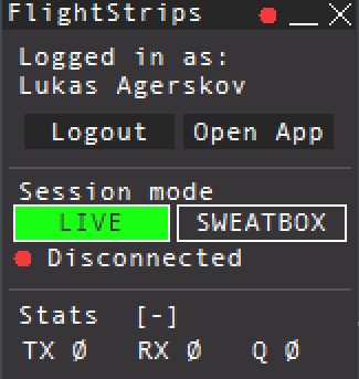
- select “OPEN APP” to open the Flightstrips window.
- Click on the FS app in your Euroscope folder
- Navigate to www.flightstrips.dk/app
If you have not yet logged into Euroscope, the FlightStrips connection will remain in standby
NOTE: You can always click CRTL+R to refresh the app

1.4 APP mode.
With Flightstrip open, you can choose “Open in APP” for the optimal aspect ratio of the program

Common Features
Containing basic information and philophies of features similar to all views of Flightstrips.......

1.1 Scopes
All configurations of Flightstrips includes various Scopes. Each position may have different versions of a scope, depending on whether the position is strictly controlling its own AOR, or also other areas as part of “top-down controlling”.
Each scope consist of four columns of similar size.
At the bottom of the each scope is the “task bar” for common features between the scopes.
e.g. EKCH_A_GND, will have the scope of AA+AD when sitting as the only apron, but will have the scope of APN ARR when sitting with a A/B_GND split.

1.2 Bays
Each of the four columns are several “bays” stacked on top of each other, all labelled with a header detailing the phase of movement where each particular bay should be used.
Strips are located within the bay generally sorted from bottom and up.
Critical bays such as bays reserved for runway occupancy have highlighted black backgrounds
A bay may, or may not also have buttons for various tactical tools applicable to that phase of movement.

1.3 Flight Strips
Flight Strips comes in two colors. A Blue strip for outbound flights, and a Yellow Strip for inbounds.
While the many different looks of strips may seem confusing at first, they are all based on the same fundamentals.
- SI Field
- Description: The transfer/assume mechanism, indicating the owner of the strip.
- Operation: Click to Transfer/Assume
- Description: The transfer/assume mechanism, indicating the owner of the strip.
- Callsign Field
- Description:The field of clicking to drag the strip around
- Operation: Click and hold to select the strip, and drag it to another bay, or
- Click to highlight to strip and click on a bay to move
- Operation: Click and hold to select the strip, and drag it to another bay, or
- Description:The field of clicking to drag the strip around
- Action Fields
- Description: Various fields of action items and information items,
- Operation: Varies from scope to scope, from bay to bay adjusting to the important
- Description: Various fields of action items and information items,
1. The SI Field
SI field has different colors depending on the state of ownership of the strip.
- Purple: when it is concerned, meaning you will receive ownership of this at some point, but not yet.
- Purple/White: In transfer towards YOU from previous controller
- White: Assumed and controlled by YOU
- White/Orange: In transfer towards next controller from YOU
- Orange: Transferred and accepted by next controller
The logic is identical to transfer/assume in COOPANS, only difference is Concerned in COOPANS is green instead of purple.
2. Callsign Field
The callsign field is one which you can click on. Clicking the callsign does two different things depending on whether or not you have assumed the strip (white color SI field).
NOT ASSUMED
Not assumed
Clicking on callsign field will open the “Callsign Menu” where you can select various submenus
- FORCE ASSUME: Takes the strip and assumed it, regardless of who is the owner.
- VIEW FPL: Opens the flightplan of the strip
ASSUMED
Assumed
Clicking on the callsign field, will select the strip, made apparent by the purple fill color of the field.
Holding the click down will allow you to drag the strip around.
Clicking on an empty space in another bay will move the strip around.
It is common procedure to click and drag the strip to establish the correct sequence within the bay
3. Action Fields
Various click spots, some to open menus, some are not clickable. It varies between the bays, and is explained in the position specific chapters.

1.4 Task Bar
Common to all scopes are the Task bar, which enables various features. It contains from left to right:
SCOPE VIEW
Preferred scope is opened by default, but can be changed if needed. Click to manually select a different scope.
WEATHER INFORMAITON ICONS
Displays the weather and runway in use information from the ATIS and Euroscope setup. Runway selection can be manually selected if needed. ATIS can be clicked to view full ATIS. Will display in RED if no ATIS is connected.
RWY STATUS ICONS
Three icons displaying each of the three runway pairs. They are black by default.
Can be selected as LOW-VIS (Orange displayed)
Can be selected as CLOSED (Red displayed)
STRIP ACTION ICONS
To the right of the runway status icons is the 4 strip action icon.
- TRF: After selecting a strip (click on callsign), clicking on TRF will open a menu to manually select any online controller to transfer a strip to.
- MRK: After selecting a strip (click on callsign), clicking on MRK will mark the strip by a purple outline for tactical purposes
- REQ: After clicking on REQ, click on any strip on your scope to request a transfer to you, to receive the strip.
- X: After selecting a strip (click on callsign), clicking on X will delete the strip.


FlightStrips contains several types of strips, which are tactical and not associated with a flight. They are identified by being distinctively different colors from the strips.

2.1 MESSAGES
All scopes contain a bay for internal messages, to communicate and coordinate with other flight strips users.
To use press one of the buttons in the Messages header. Write your own, or select the most commonly used standard messages.
Select the specific position you want to write your message to, or select BROADCAST to send the message to everybody using FlightStrips. Once a message is sent, it can be individually deleted by each controller by clicking on the “X”.
All messages are subject to VATSIM-Scandinavia rules and VATSIM Code of Conduct limitations.

2.2 MEMORY AIDs
Memory aids are types of strips a controller can activate to put a condition or reminder to an aircraft.
Clicking the MEMAID button in the appropriate headers, opens the MEMAID window which is similarly structured to MESSAGES.
To make a flight specific memory aid, select the flight before clicking memory aid, and you will see the airplane in parenthsis in the MEM AID strip.

2.3 CROSSING
CROSSING strip takes a bright yellow color and is a tactical reminder when an aircraft in one bay, as to cross the path of an aircraft in another bay.
To create a crossing strip, click on the “X” in the yellow box above a qualifying bay. The strip is produced instantly.
Once produced, you can move it around, to the correct position to reflect where traffic will cross.
Any controller can force ownership of the “CROSSING” strip by clicking on the strip and selecting “FORCE ASSUME”. A “CROSSING” strip should be deleted once the condition is no longer present.
Examples of use are:
GW_TWR needs to cross 22L on the way to Apron East. Crossing strip activated by A_TWR to signify gap where GW can cross
A_TWR needs to taxi via C and RWY30 to K3. Crossing strip activated by D_TWR to signify gap between departures A_TWR can cross.

2.4 LAND/START
LAND and START strips takes bright orange colors. This strip is to mark an aircraft landing or taking off on a runway, where the strip may not actually be present.
Uniquely to LAND/START strips an hourglass is present, which can be clicked to start a time. This can be useful for Wake Turbulence separation.
Examples of use are:
A_TWR needs a landing on 22R. Strip can be activated to signify landing on 22R.
A_TWR needs a low pass on RWY30. Strip can be activated on TWY DEP to ensure no flights are crossing 12/30 while aircraft performs low pass.
CLR DEL - Operation

1.1 Overview
- Scope name: CLR DEL
- Used by: EKCH_DEL
[PIC]

1.2 Scope Design
Column 1 | Column 2 | Column 3 | Column 4 |
OTHERS1 | SAS1 | CLEARED | PUSHBACK2 (Passive) |
NORWEGIAN1 | MESSAGES2 | TWY DEP2 (Passive) |
- 1: Categories combined under PLANNED DEP
- MESSAGES and Passive bays will not be expanded upon. Refer to chapter 2 for details.

1.3 PLANNED DEP
Column 1 and 2 and the bays associated (OTHERS, SAS, NORWEGIAN) represent planned departures, which does not yet have their ATC Clearance. There is no SI field, as the strips does not have an owner at the planned departure stage i.e. strips CANNOT be assumed and transferred.
Strip design

- Callsign. Click to open callsign menu
- Destination / Stand. Click either to open “ATC CLEARANCE MENU”
- EOBT. Informational only
- TOBT. Informational only
- CTOT. Informational only
- TSAT. Informational only

1.4 CLEARED
Column 3 and the bay CLEARED is for aircraft who has received the ATC Clearance and is automatically transferred to the next controller.
Strip design
- Callsign. Click to open callsign menu
- Destination / Stand number. Click either to open Flight Plan
- EOBT. Informational only
- CTOT. Informational only
- TOBT. Informational only
- TSAT. Informational only


2.1 ATC Clerance
When an aircraft calls for ATC Clearance, click on Destination / Stand to open the ATC CLEARANCE MENU, to read the clearance to the pilot.
[GIF]
Once ATC Clearance is read back by the pilot click on CLD to confirm the clearance. Aircraft is immediately moved from the associated “PLANNED DEP” bay to “CLEARED” bay.

2.2 Pre-Departure Clearance (PDC)
Upon reception of a PDC, strip will blink for five seconds following by either:
- Moved to CLEARED bay if no errors detected. Strip will remain solid purple until pilot acknowledges the clearance.
- Maintained in PLANNED DEP bay highlighted in bright yellow, if one of the following conditions were sensed:
- Error in FPL
- Custom message inserted in remarks.
In case of errors or remaks, open up the ATC CLEARANCE MENU and assign the clearance manually, by clicking CLD. If you are unable to provide a clearance to the pilot, click REVERT TO VOICE next to CLD. Either action will send the appropriate message to the pilot via PDC.

2.3 Completion of ATC Clearance
Upon move to CLEARED bay, the SI field becomes apparent in an orange color. This is because the strip is already transferred to next controller.
As Delivery you must immediately hand over the aircraft to next frequency.
If EKCH_DEL are responsible for START-UP in addition to normal responsibilities, the SEQ PLN scope shall be manually selected and controlled through there.
CDM and Startup approvals CANNOT be controlled from CLR DEL scope. EKCH_DEL must be on SEQ PLN scope when in charge of CDM


3.1 ATC CLEARANCE DIALGUE
The ATC Clearance dialogue is divided into three sectors. Departure section, Arrival Section and general information.
3.2 NEW
3.3 PLANNED
