Software & Manuals
Here is an overview of all related software as well as manuals and guides. Usage procedureres found here as well as in the GOP
- EuroScope ATC Client
- CDM - Collaborative Decision Making Tool
- Arrival Load Balancer - ALB
- VACS
- Flightstrips
- FlightStrips - User Guide
EuroScope ATC Client
Installation guides, modification and troubleshooting
Introduction
VATSCA releases its sector files in collaboration with AeroNav through the dedicated AeroNav sector file website. This means that sector files for Denmark must be manually installed and applied in EuroScope in order to function correctly. They cannot be downloaded automatically.
This guide will walk you through the initial installation of EuroScope, followed by your first sector file installation, and finally how to update your sector files when new versions are released.
The Copenhagen FIR currently uses the following version of EuroScope: https://euroscope.hu/install/EuroScopeSetup.3.2.3.2.msi ↗
Installation
Table of Contents
Prerequisites
Before installing EuroScope, make sure to download and install the latest Microsoft C++ Redistributable packages. These can be downloaded from here ↗
Installation of Euroscope
The installation of EuroScope is straightforward. Simply follow the installer instructions. The only step requiring input is selecting the folder where you want the files installed.
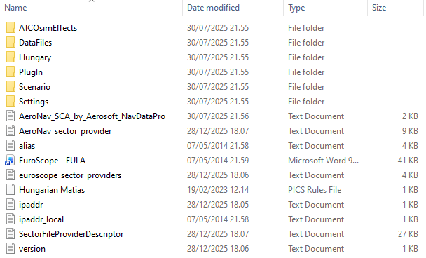
Click "Next" to reach the location selection screen:
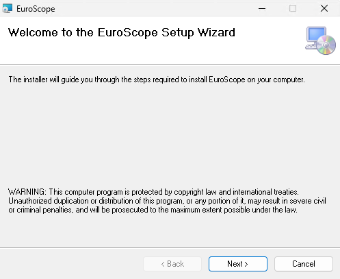
Select the folder where you would like EuroScope to be installed. The recommended location is the C: drive.
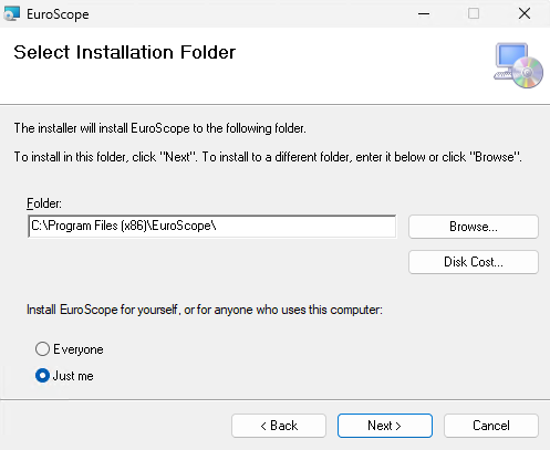
Then click "Next" again to proceed to the final confirmation screen.
And that's it, the installation is complete! Click "Close" to exit the installer.
Your first instinct might be to launch EuroScope, but don't do that just yet.
First, install your sector files as described below.
Installation of Sector Data
Begin by opening File Explorer. You can do this easily by pressing Windows + E.
Next, locate your AppData folder. The easiest way is to click the address bar, type "%appdata%", and press Enter; this will take you directly to the folder.

Locate your EuroScope folder. It should look roughly like this.
Next, go to files.aero-nav.com/SCA ↗. Log in using your VATSIM/Navigraph account, then download the ZIP file named "EKDK Full-Package".
Once downloaded, open the ZIP file. Inside, you should see a set of files and folders, including the EKDK folder.
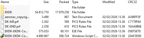
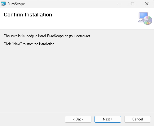
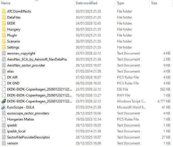
Copy all contents of the ZIP file into your EuroScope installation directory. After doing so, your EuroScope folder should resemble the structure shown below. Additionally, install the modified EuroScope font included in the EKDK Sector Data
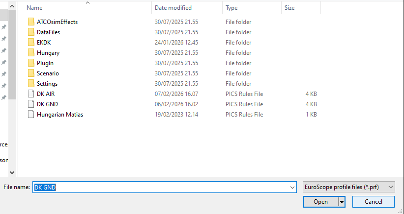
You can now open EuroScope for the first time. Once it has loaded, you'll be greeted by the following window. If you're just starting out as an observer for your S2 training, select the "DK NITOS" file and click "Open".
Updating sectorfiles
Updating of Sectorfiles
Sector files are updated:
- Approximately every 28 days, when a new AIRAC cycle is released;
- Whenever a major change is published in our internal files.
When a new sector file update is released, go to https://files.aero-nav.com/SCA ↗.
Download the "EKDK EKDK_FIR-Update-Only" package instead of the full package.
Begin by opening File Explorer. You can do this easily by pressing Windows + E.
Next, locate your AppData folder. The easiest way is to click the address bar, type "%appdata%", and press Enter; this will take you directly to the folder.

Locate your EuroScope folder.
As with the initial installation, open the ZIP file and copy all contents into your EuroScope installation directory. You will be prompted to overwrite existing files; make sure to select "Yes".
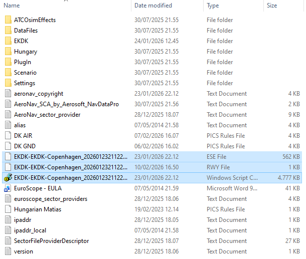
At your own discretion, it can be a good idea to delete the following three files before installing new sector files. This helps ensure that EuroScope does not accidentally load outdated or additional ESE or RWY files when launching.
This can happen because some file names are not always identical and therefore may not be overwritten during the update process. This step is not always necessary, but it can be beneficial in certain cases.
CDM - Collaborative Decision Making Tool
What is CDM
CDM is a modern tool helping us to manage traffic flow, both in and out of Copenhagen but also to ensure capacity is not breached other places. Likewise it is used by other airports to modulate traffic flow to help our sectors
CDM is MANDATORY for ALL online controllers to different extents!
-
ATFCM is management of CTOTs as is mandatory for ALL controllers regardless of position as long as traffic load allows. This is discussed under "Simplified CDM Procedures"
-
A-CDM is management of TSAT for sequencing within the airports, and is mandatory for TWR/GND controllers to the extent feasable. This is discussed under "Expanded CDM Procedures"
-
CDM Module should always be running regardless
Abbreviations and Explanations
CDM: Collaborative Decision Making: patent term concerning flow restriction and planning to ensure appropriate ATC capacity during all phases of flight
ATFCM: Air Traffic Flow Control Management: Tool to modulate flights based on sector capacity by use of CTOTs to modulate traffic limitation around Europe.
A-CDM: Airport-Collaborative Decision Making: local airport flow regulations based on turnaround and TOBTs to ensure planes taxi and take off in a manner avoiding congestion
EOBT : Estimated off block time: Time filed by the flightplan as planned start up time
TOBT: Target off block time: Time filed by the pilot after entering airplane as proposed start up time
TSAT: Target Start Up Approval Time: System created time for start up approval to comply with CDM/ATFCM
ASRT: Requested Start Up Time: Time pilot has requested start up, to search for earlier TSAts
CTOT: Calculated Takeoff Time: Time the pilot should take of at +10/-5 min, to comply with ATFCM.
What does it all mean?
Quick Breakdown for the basic rules
EOBT is always filed as part of the flight plan
TOBT is filed and changed during the boarding as predicted ready time may be changed back and forth. Pilot can freely choose this time. It is essentially a "Fine Tuning" of EOBT. A controller may also set this time.
TSAT is the time the CDM has targeted the pilot to start up on. This is based on
- 40 slots pr. hour meaning a takeoff time every 90 seconds
- Taxi time to the runway
- Making extra separation between two identical SIDs
- Finding a slot - taxi time which is as close as possible to the pilot filed TOBT.
ASRT is purely a marker you use to remind yourself pilot has requested start-up
ASAT is the time he has been given startup which is also in a way a marker.
Pilots KNOW their TOBT (it is filed by them)
Pilots DO NOT know their TSAT (It is constantly changing and is calculated by the system)
What to expect from Pilots
- Pilot have a off block time or EOBT. This is filed with the flightplan
- TOBT is automatically calculated and will initially be identical to the EOBT
- Pilots will access "vats.im/vgds" to "Confirm" their off block time. This should be done by pilots who want to avoid extensive delay, but is not mandatory
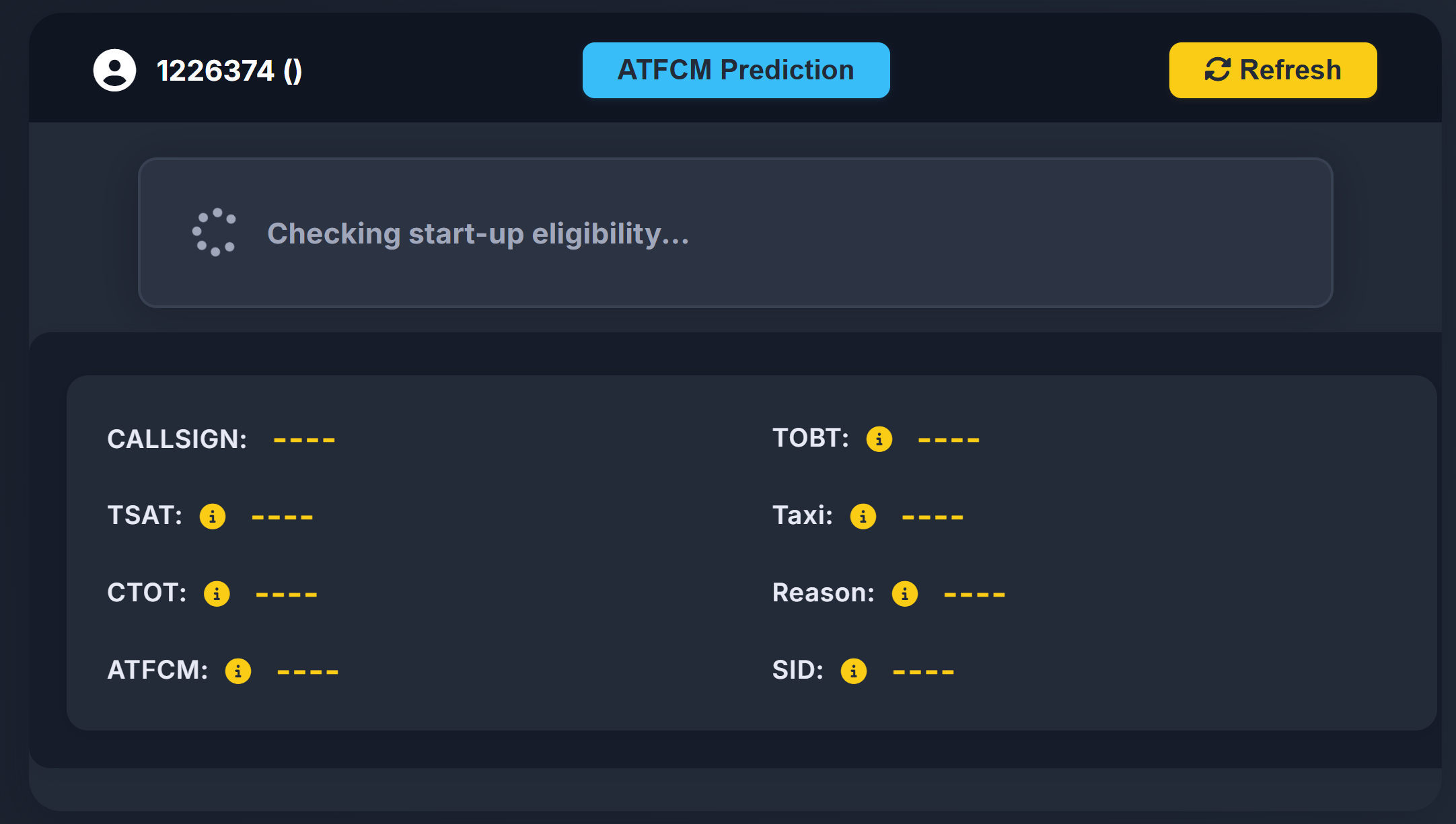
Pilots shall call within +/- 5 minutes of their TOBT (the one they know)
Start-up shall only be granted within +/- 5 minutes of the TSAT (the calculated one)
Simplified CDM Procedures (APP/CTR)
Starting CDM (All Controllers)
As the first thing when you log on you must activate CDM to use it
Write .cdm master EKCH to activate!

How to do controller change correctly
- The Old controller changes to Slave with command .cdm slave EKCH
- Once there are no master controllers, the new controlles gets the master "role" by writing .cdm master EKCH
Simplified CDM Procedures (Top-down by APP/CTR)
This part of CDM is known as the ATFCM
Simplified CDM procedures are done from departure list. Please know that:
- You are completely allowed to perform expanded CDM procedures if your capacity allows
- You MUST adhere to displayed CTOT for takeoff
- You may ignore TSATs without CTOTs, if workload is too heavy.
Reference Material
Press on the top of the TSAT column where it says TSAT! This orders the departure list after TSATs and makes it easier to manage
Actions for simplified CDM procedures are identical as expanded, but with more freedom
You departure list now features a TOBT, a TSAT and a CTOT.

TOBT shows the estimated time of departure filed by the pilot.
- TOBT: Is Light green when the time is valid but not yet within the window for startup.
- TOBT: Is Dark green when the time is within time for startup approval.
- TSAT: Is Light green when the time is valid but not yet within the window for startup.
- TSAT: Is Dark green when the time is within time for startup approval.
- TSAT: Is Yellow when the time is within 1 minute from expiring
- TSAT is blank if time is expired.
- CTOT: Is Green, Orange or Red depending on the type of restriction triggering the CTOT.
Procedures
Aircraft calls for ATC Clearance
If CTOT is present: Advise of CTOT. You MUST in this case adhere to the TSAT. Advise pilot about CTOT!
If no CTOT: No further action required at this stage
Aircraft calls for STARTUP/PUSHBACK
- Right click on TOBT to signal aircraft ready for startup.
if CTOT is present:
- Adhere to TSAT Displayed . If TSAT is not yet within startup window (Light green), pilot must wait.
- When TSAT is within startup window (Dark Green) (+/- 5min) Start-up can be approved.
if no CTOT is present
- Start and push can be approved, regardless of TSAT time
- Be aware that non-adherance to TSATs may result in longer waiting times at the runway.
Explanations
NIL
Expanded CDM Procedures (TWR/GND/DEL)
Starting CDM (All Controllers)
As the first thing when you log on you must activate CDM to use it
Write .cdm master EKCH to activate!
How to do controller change correctly
- The Old controller changes to Slave with command .cdm slave EKCH
- Once there are no master controllers, the new controlles gets the master "role" by writing .cdm master EKCH
Expanded CDM Procedures (TWR/GND/DEL)
This is both conducting ATFCM via CTOTs and A-CDM through use of TSATs
Expanded CDM procedures are done from Startup list, but can be done via departure list for TWR. Please know that:
- You should adhere to A-CDM procedures unless traffic load is low, either through Departure list or Startup list.
- You MUST adhere to displayed CTOT for takeoff
Reference Material
Press on the top of the TSAT column where it says TSAT! This orders the departure list after TSATs and makes it easier to manage
With expanded mode there is a lot more information, but procedures are very similar
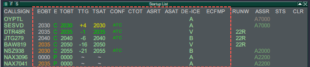
Descriptor
There are four main descriptor of times (EOBT, TOBT, TSAT, CTOT), separated by three descriptors (E, TTG, CONF), and an additional four additional items (ASRT, ASAT, DE-ICE, ECFMP).
- EOBT: Estimated Off Block Time
- The pilot filed off block time from the flightplan (e.g. Simbrief). The one passengers shows up for.
- TOBT: Target Off Block Time.
- The pilot filed off block time, via our CDM tool to confirm actual time of start-up readiness.
- TSAT: Target Start-up Approval Time.
- The time our system calculates based off the TOBT, to have the pilot fit into the sequence.
- For internal capacity mainly
- CTOT: Calculated Takeoff Time
- A Takeoff time at which the aircraft must depart within -5/+10 min of. TSAT is adjusted accordingly.
- For external capacity (ECFMP, ATFCM)
(Color) Coding
EOBT
TOBT
TSAT
CTOT
LIGHT GREEN
--
Valid, but not yet Active
--
DARK GREEN
--
Active
By CDM Server*
YELLOW
--
TOBT+4
TSAT+4
Default Color
RED
Flight Suspended
--
By CAD*
ORANGE
EOBT >5min from TOBT
By Manual Event*
WHITE
Default color
*Not important to know
- E: A descriptor about the validity of the filed TOBT.
- TTG: Time until the TSAT (- equals time to go, +equals past TSAT)
- CONF: A descriptor if the TOBT has been confirmed ( or altered) by either "pilot" or "ATC"
-
(Color) Coding
E
TTG
CONF
DARK GREEN
Correct (C) or Passed (P)
-35min until +3 min
Default Color
YELLOW
--
+4min until +5 min
TSAT+4
RED
Invalid (I)
--
-
- ASRT: Actual Start-up Request Time
- The pilot requested start-up if done so before TSAT is active.
- ASAT: Actual Start-up Approval Time
- When start-up approved (STUP or PUSH in Status), ASAT activates and rest of line goes gray.
- DE-ICE: De Icing assigned
- De-ice is required for the pilot, hence taxi out time will be extended.
- ECFMP: European Central Flow Management Position
- A note on what is the origin of a particular flow measure. Only for information.
Procedures
Procedures depends on whether you are handling SEQ only or DEL+SEQ.
Aircraft calls for ATC Clearance (if within AOR)
If CTOT is present: Advise pilot about CTOT!. Advise on earliest startup time (TSAT)
If no CTOT: No further action required at this stage.
Aircraft calls for STARTUP/PUSHBACK
Check your timings and note:
- If TSAT is Dark Green, Start-up can be approved.
- If TSAT is Light Green, Pilot is still more than 5 minutes early. he must wait.
- If TSAT is Yellow Start-up can be approved, but be quick, it will soon expire.
- If TSAT is Blank, Flightplan expired and new TOBT must be filed.
If TSAT is Light Green or a CTOT is present or TOBT is Invalid (expired), try to improve it by sending a "Ready message" by *right clicking on the TOBT. This updates the TOBT to current time, and tries to recalculate everything to look for an earlier time.
If TSAT remains Light Green after that, Start-up cannot yet be approved.
- Click ASRT to remind that a request has been made by the pilot
- Approve Startup when TSAT turns Dark Green
When start-up approved
- Update Status to STUP or PUSH to activate ASAT, and blank out the rest of the times. Aircraft is released.
Flow Chart
Right click on image and select "Open in new tab" to see picture in higher resolution

Arrival Load Balancer - ALB
Manual
https://sodgaard.github.io/Euroscope-ALB_Releases/
VACS
We are starting to use a new communication tool, for easier coordination. This will give a better way of getting in contact with the different controllers, needed for coordination.
1. Download Instructions
DOWNLOAD VACS
2. Installation and Configuration
Install it and setup your audio preferences by clicking on the SETTINGS 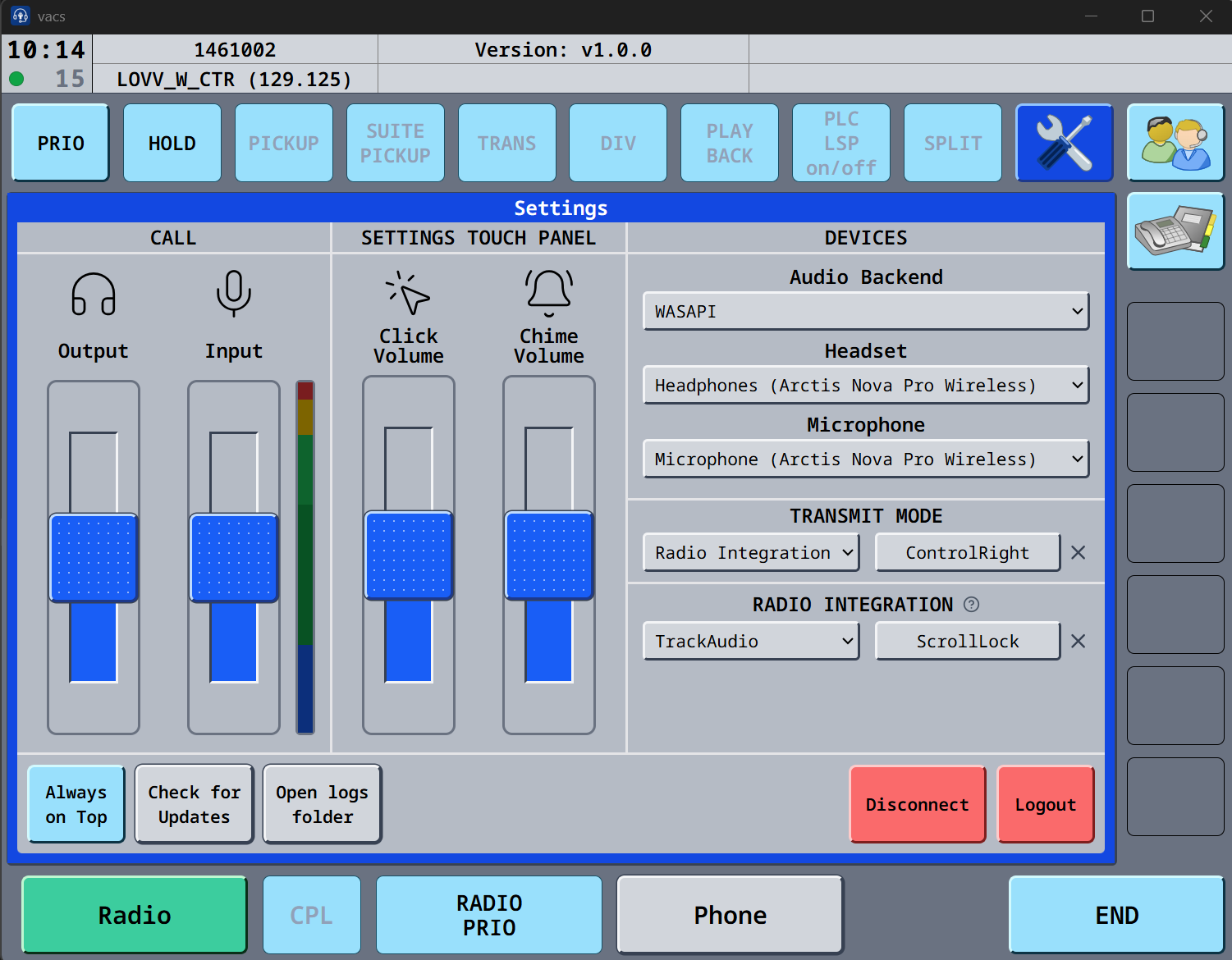
If you cannot see input impacts, click on the VU meter, and you can now see the input. Under transmit mode, you can choose Push to mute, and use the button, as you are using in trackaudio, this way the mic in VACS will be muted if in a call.
3. Profiles
Profile is now automatically fetched from the server.
4. Usage
You now call a station instead. Simply select the ATC station you want to reach (e.g., "CH TWR", "DK B", "DK UA"), and vacs will automatically route your call to the controller currently in charge of that station. Top-down coverage and sector inheritance typical to VATSIM are handled automatically, ensuring your call always reaches the right person. If a station is covered by multiple controllers (e.g., during a coordinator/mentoring session), they will all receive the call and can choose to answer it.
This brings coordination much closer to its real-life equivalent - you dial a position rather than a specific person.
Additionally, you can now select the station you are calling from. This gives the recipient more context, indicating which region they should expect to coordinate with you on.
- Single click on a station you control sets it as a temporary call source. Your next call will originate from this station, then reset automatically.
- Double click (clicking the same key again) sets it as the default source, which persists across calls.
- Clicking again unsets it.
You can have both a temporary and a default source selected at the same time. The temporary source takes priority for the next call and then reverts to the default.
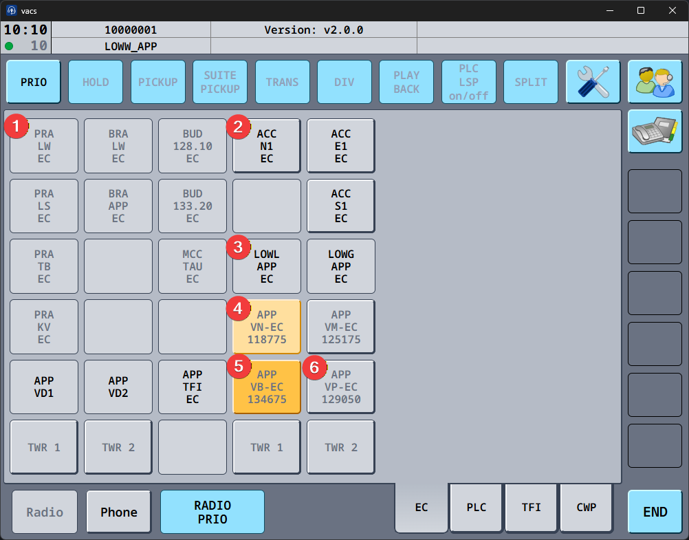
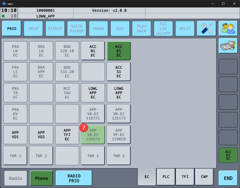
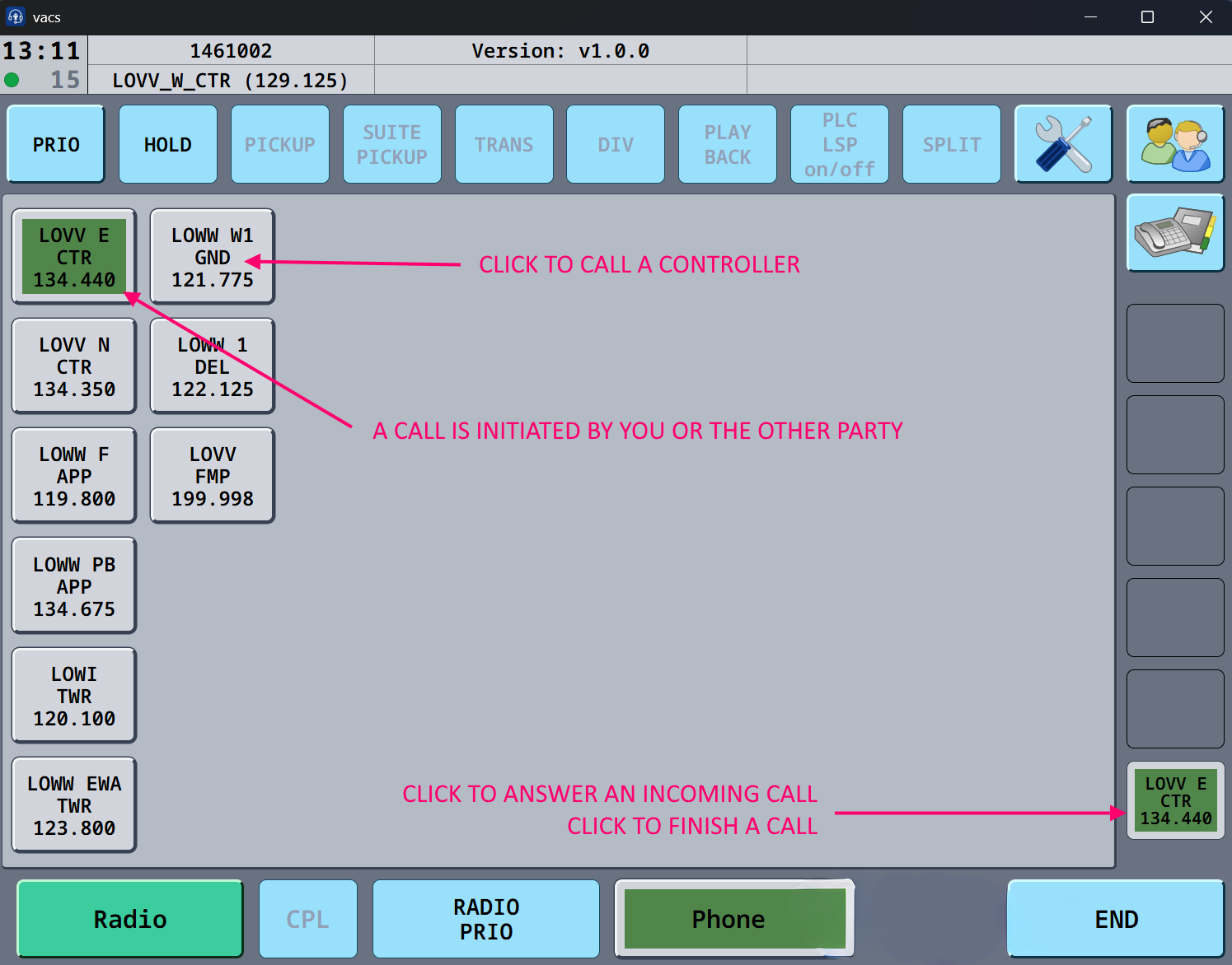
To Call a controller : Click on the icon of the controller you want to call. The open line appears in the bottom right corner in green, and a call tone appear until the VACS line is picked up.
To answer a call: The green icon in the bottom right, will appear signifying the controller trying to call you. Press that bottom right icon, to answer the call.
to finish a call: Click the green icon in the bottom right corner. The icon will disappear, and all icons turn gray, signifying no active call is ongoing.
Flightstrips

The project can be found on Github and docs are docs.flightstrips.dk
FlightStrips - User Guide
Chapter 1 - Introduction & Installation
Welcome to FLIGHTSTRIPS. A program developed by VATSIM-Scandinavia for traffic management, automatic coordination and traffic flow optimization.
This user guide contains 10 Chapters outlining all you need to know to correctly operate all positions with FlightStrips within EKCH.

1.1 Download
FlightStrips is included with the Danish sector file package.
- There is no installation or download process as the program is web-based.
- There is no action in Plug-ins needed in Euroscope

1.2 Activation
When opening Euroscope the FlightStrips dialogue opens, prompting you to login if not already

The login is saved for ~30 days, and will only need to be revalidated if not utilized within that time.

1.3 Opening FlightStrips
Once login is complete, you have several options of how to open flightstrips
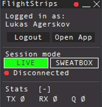
- select “OPEN APP” to open the Flightstrips window.
- Click on the FS app in your Euroscope folder
- Navigate to www.flightstrips.dk/app
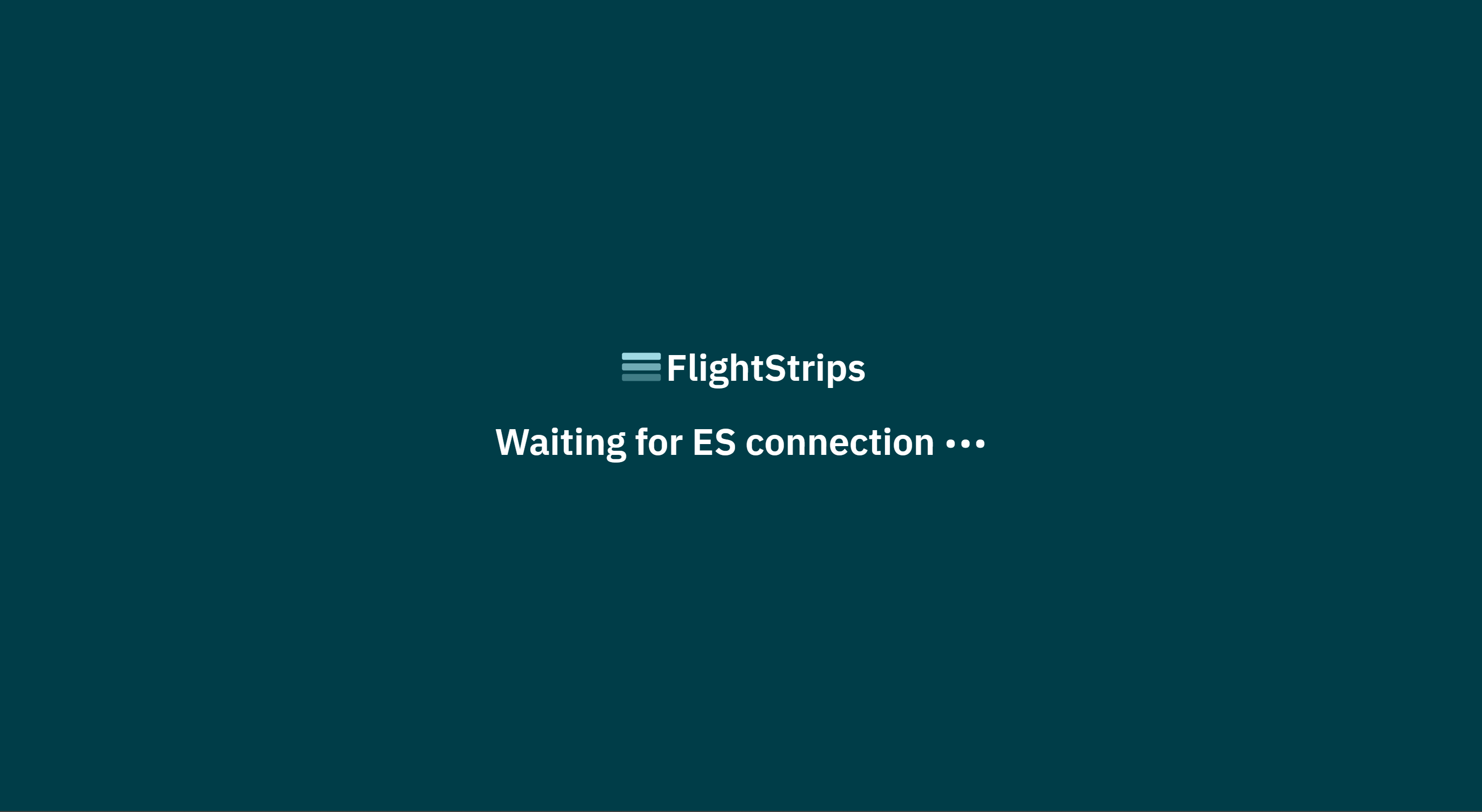
If you have not yet logged into Euroscope, the FlightStrips connection will remain in standby
NOTE: You can always click CRTL+R to refresh the app

1.4 APP mode.
With Flightstrip open, you can choose “Open in APP” for the optimal aspect ratio of the program

Chapter 2 - Strip Design
1. Flight Strips
Flight Strips comes in two colors. A Blue strip for outbound flights, and a Yellow Strip for inbounds.
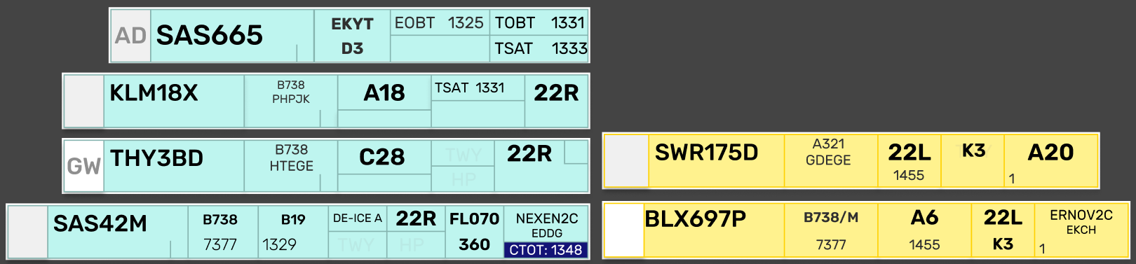
While the many different looks of strips may seem confusing at first, they are all based on the same fundamentals.
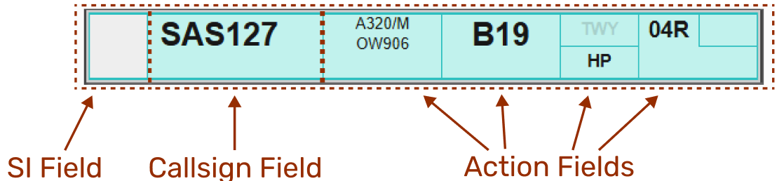
- SI Field
- A rectangular field, in three possible color combinations, with out without a two letter identifier.
- Description: The transfer/assume mechanism, indicating the owner of the strip.
- Operation: Click to Transfer/Assume
- Callsign Field
- A large field, containing the callsign of the aircraft the strip concerns.
- Description:The field of clicking to drag the strip around
- Operation: Click and hold to select the strip, and drag it to another bay, or
- Click to highlight to strip and click on a bay to move
- Operation: Click and hold to select the strip, and drag it to another bay, or
- Action Fields
- Everything else in the strip.
- Description: Various fields of action items and information items, depicted in six (6) possible formats.
- Operation: Each combination of action fields, depends on what is relevant for the stage of flight.
1. SI Field
The SI field has different colors depending on the state of ownership of the strip.
- Purple: when it is concerned, meaning you will receive ownership of this at some point, but not yet.
- Purple/White: In transfer towards YOU from previous controller
- White: Assumed and controlled by YOU
- White/Orange: In transfer towards next controller from YOU
- Orange: Transferred and accepted by next controller
The logic is identical to transfer/assume in COOPANS, only difference is Concerned in COOPANS is green instead of purple.
2. Callsign Field
The callsign field is one which you can click on. Clicking the callsign does two different things depending on whether or not you have assumed the strip (white color SI field).
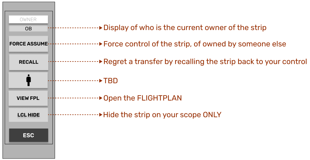
NOT OWNED
Not assumed
Clicking on callsign field will open the “Callsign Menu” where you can select various submenus
OWNED
Assumed
Clicking on the CALLSIGN field, will select the strip, made apparent by the purple fill color of the field.
It is common procedure to click and drag the strip to establish the correct sequence within the bay
- Holding the click down will allow you to drag the strip around.
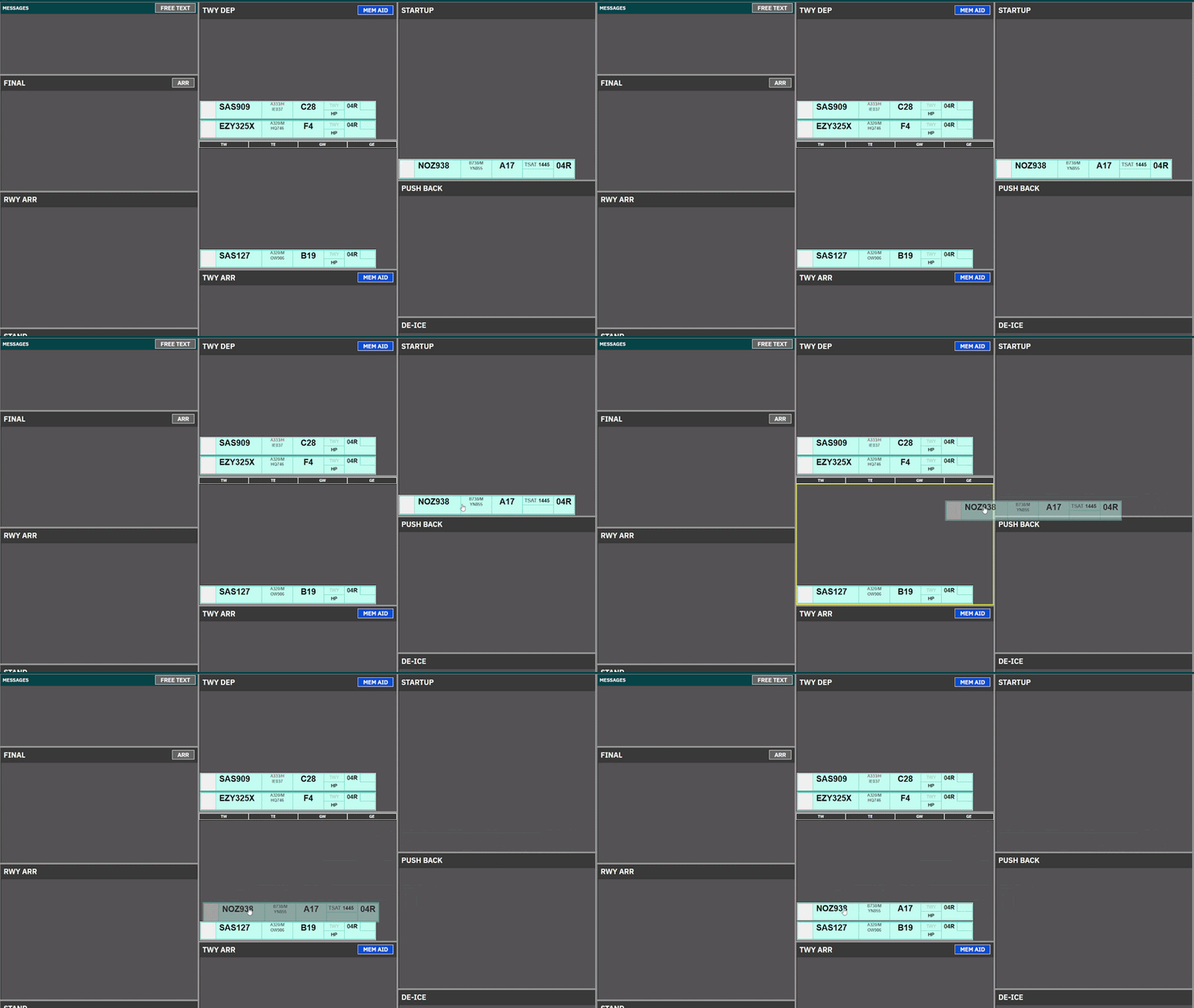
- Clicking on Strip and subsequently clicking on another bay will move the strip.
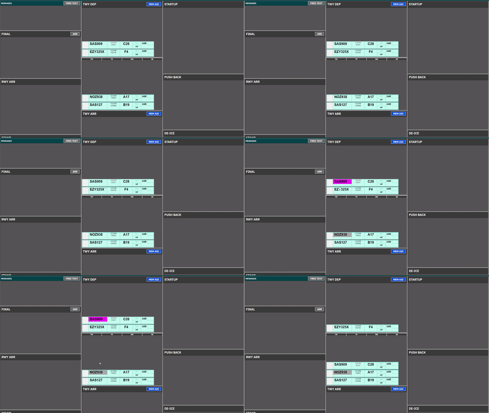
3. Action Fields
Various click spots, some to open menus, some are not clickable. There are six different version of Strips, each with action fields which are relevant to the phase of flight for the strip.
Over the different scopes, several different visual configurations are possible, and generally depending on the combination of Scope and Bay.
REF. | STRIP NAME | USED BY |
1.1 | DEL/SEQ Strip | CLR DEL & SEQPLN to provide ATC Clearance and CDM management. |
1.2 | START/PUSH Strip | ALL Controllers in STARTUP & PUSHBACK Bays to facilitate such. |
1.3 | TAXI-OUT STRIP | For Taxi-Out instructions, used by APRON for relevant holding points |
1.4 | TAXI-IN STRIP | For Taxi-In instructions, used by APRON for relevant stand info. |
1.5 | Expanded TAXI-OUT STRIP | For Taxi-Out instructions, used by TOWER for including departure info. |
1.6 | Expanded TAXI-IN STRIP | For Taxi-in, Used by TOWER for information on LDG RWY, timings and STAR. |
In the following sections we will go through the buildup of each strip, for you to reference. The actual usage of strip is described in each “operation” chapter.
END OF SECTION

1. Strip Design

1.1 DEL/SEQ Strip
DEL/SEQ Strip is a strip, containing only CDM information, and the needed clickspots to assign an ATC Clearance and Startup. This strip is used in
- All bays of the CLR DEL Scope.
- STARTUP bay of the SEQ PLN Scope.
DEL / SEQ Strip | |||
| |||
ID | Name | Description | Clickspot |
1 | SI Field | Click to Initiate Transfer | Yes |
2 | Callsign | Click to mark or open callsign menu. | Yes |
3 | Dest/Stand | Click on either to open ATC Clearance Dialogue | Yes |
4 | EOBT | Information on FPL filed EOBT | No |
5 | CTOT | CTOT assigned. Color coding/ops as per Chapter 8 - CDM Operation | No |
6 | TOBT | Information on latest TOBT. Color coding/ops as per Chapter 8 - CDM Operation | Yes* |
7 | DEP RWY | Information on latest TOBT Color coding/ops as per Chapter 8 - CDM Operation | No |


*Only in SEQ PLN Scope

1.2 START/PUSH Strip
PUSH/START Strip is a strip containing simplified CDM info as well as the features needed to provide pushback and engine starts. It is used in:
- All PUSHBACK and STARTUP bays on the scope with exception of:
- STARTUP bay in SEQ PLN
PUSH / START Strip | |||
| |||
ID | Name | Description | Clickspot |
1 | SI Field | Click to Accept Transfer Click to Initiate Transfer | Yes |
2 | Callsign | Click to Mark or open Callsign Menu | Yes |
3 | Reg / Type | Open FlightPlan | Yes |
4 | Stand | Open Airport Map for selection of clearance limit | Yes |
5 | DE-ICE | Showing platform for De-Ice if requested. Accompanied by snow icon below Ref/Type | No |
6 | TSAT | Information on latest TSAT. Color coding/ops as per Chapter 8 - CDM Operation | Yes |
7 | CTOT | Information on latest CTOT Color coding/ops as per Chapter 8 - CDM Operation | No |
7 | DEP RWY | Click to manually change Departure Runway | Yes |



1.3 TAXI-OUT Strip
TAXI-OUT Strip is used on TWY DEP for specifically Kastrup Apron controllers. This means it is visible only at:
- TWY DEP bay for following scopes:
- AA+AD, APRON DEP, APRON ARR
TAXIOUT Strip | |||
| |||
ID | Name | Description | Clickspot |
1 | SI Field | Click to Accept Transfer Click to Initiate Transfer | Yes |
2 | Callsign | Click to Mark or open Callsign Menu | Yes |
3 | Reg / Type | Open FlightPlan | Yes |
4 | Stand | Informational only (in case of return to stand) | No |
5 | DE-ICE | Showing platform for De-Ice if requested. Accompanied by snow icon below Ref/Type | No |
6 | TWY HS | Taxi clearance limit. Click to assign hold short | Yes |
7 | HP | Holding point. Click to assign Holding Point. | Yes |
7 | DEP RWY | Click to manually change Departure Runway | Yes |


1.4 TAXI-IN Strip
PUSH/START Strip is used on TWY ARR for specifically Kastrup Apron controllers. This means it is visible only at:
- TWY ARR bay for following scopes:
- AA+AD, APRON DEP, APRON ARR
TAXI-IN Strip | |||
| |||
ID | Name | Description | Clickspot |
1 | SI Field | Click to Accept Transfer | Yes |
2 | Callsign | Click to Mark or open Callsign Menu | Yes |
3 | Type / Reg | Click to open Flightplan | Yes |
5 | ARR RWY | Informational only | No |
6 | LDG Time | Informational only | No |
7 | TWY HS | Click to select taxi clearance limit Standard feeder route on default | Yes |
9 | Stand | Click to open Stand Assignment Tool | Yes |
10 | Marshaller | Detects if pilot has GSX through FlightStrips. Appears only if that is the case. Number denotes stop line | TBA |


1.5 Expanded TAXI-OUT Strip
Expanded TAXI-OUT Strip is used on TWY DEP for specifically Kastrup Tower controllers. The purpose of this strip is to accomendate more departure relevant information such as initial climb and assigned headings.
It is used for
- TWY DEP, RWY DEP and AIRBORNE bay for following scopes:
- GE+GE, TW+TE, TWR+GND
Expanded TAXI-OUT Strip | |||
| |||
ID | Name | Description | Bay |
1 | SI Field | Click to Accept Transfer Click to Initiate Transfer |
|
2 | Callsign | Click to Mark or open Callsign Menu |
|
3 | Type | Informational only |
|
4 | Squawk | Informational only |
|
5 | Stand | Informational only |
|
6 | EOBT | Informational only |
|
7 | DE-ICE | Showing platform for De-Ice if requested. |
|
8 | TWY HS | Taxi clearance limit. Click to assign hold short |
|
9 | DEP RWY | Click to change Departure Runway |
|
10 | HP | Click to assign Holding Point. |
|
11 | CFL | Cleared Flight Level. Click to change. SID level default |
|
12 | HP | Assigned Heading. Click to change. Blank by default |
|
13 | SID/Destination | Click to open FlightPlan |
|
14 | CTOT | Information only Color coding/ops as per Chapter 8 - CDM Operation |
|


1.6 Expanded TAXI-IN Strip
Expanded TAXI-IN Strip is used on TWY ARR for specifically Kastrup Tower controllers.
It is used for
- TWY ARR and RWY ARR and FINAL bay for following scopes:
- GE+GE, TW+TE, TWR+GND
Expanded TAXI-IN Strip | |||
| |||
ID | Name | Description | Bay |
1 | SI Field | Click to Accept Transfer Click to Initiate Transfer |
|
2 | Callsign | Click to Mark or open Callsign Menu |
|
3 | Type / WTC | Informational only |
|
4 | Squawk | Informational only |
|
5 | Stand | Click to open Stand Assignment Tool |
|
6 | LDG Time | Informational only |
|
7 | ARR RWY | Informational only |
|
8 | TWY HS | Click to select taxi clearance limit Standard feeder route on default |
|
9 | STAR/Dest | Click to open FlightPlan |
|
10 | Marshaller | Detects if pilot has GSX through FlightStrips. Appears only if that is the case. Number denotes stop line |
|

Chapter 3 - Common Features
Containing basic information and philophies of features similar to all views of Flightstrips.......

1.1 Scopes
All configurations of Flightstrips includes various Scopes. Each position may have different versions of a scope, depending on whether the position is strictly controlling its own AOR, or also other areas as part of “top-down controlling”.
Each scope consist of four columns of similar size.
At the bottom of the each scope is the “task bar” for common features between the scopes.
e.g. EKCH_A_GND, will have the scope of AA+AD when sitting as the only apron, but will have the scope of APN ARR when sitting with a A/B_GND split.

1.2 Bays
Each of the four columns are several “bays” stacked on top of each other, all labelled with a header detailing the phase of movement where each particular bay should be used.
Strips are located within the bay generally sorted from bottom and up.
Critical bays such as bays reserved for runway occupancy have highlighted black backgrounds
A bay may, or may not also have buttons for various tactical tools applicable to that phase of movement.

1.3 Flight Strips
Flight Strips comes in two colors. A Blue strip for outbound flights, and a Yellow Strip for inbounds.
While the many different looks of strips may seem confusing at first, they are all based on the same fundamentals.
- SI Field
- A rectangular field, in three possible color combinations, with out without a two letter identifier.
- Description: The transfer/assume mechanism, indicating the owner of the strip.
- Operation: Click to Transfer/Assume
- Callsign Field
- A large field, containing the callsign of the aircraft the strip concerns.
- Description:The field of clicking to drag the strip around
- Operation: Click and hold to select the strip, and drag it to another bay, or
- Click to highlight to strip and click on a bay to move
- Operation: Click and hold to select the strip, and drag it to another bay, or
- Action Fields
- Everything else in the strip.
- Description: Various fields of action items and information items, depicted in six (6) possible formats.
- Operation: Each combination of action fields, depends on what is relevant for the stage of flight.
1. The SI Field
SI field has different colors depending on the state of ownership of the strip.
- Purple: when it is concerned, meaning you will receive ownership of this at some point, but not yet.
- Purple/White: In transfer towards YOU from previous controller
- White: Assumed and controlled by YOU
- White/Orange: In transfer towards next controller from YOU
- Orange: Transferred and accepted by next controller
The logic is identical to transfer/assume in COOPANS, only difference is Concerned in COOPANS is green instead of purple.
2. Callsign Field
The callsign field is one which you can click on. Clicking the callsign does two different things depending on whether or not you have assumed the strip (white color SI field).
NOT OWNED
Not assumed
Clicking on callsign field will open the “Callsign Menu” where you can select various submenus
OWNED
Assumed
Clicking on the CALLSIGN field, will select the strip, made apparent by the purple fill color of the field.
It is common procedure to click and drag the strip to establish the correct sequence within the bay
- Holding the click down will allow you to drag the strip around.
- Clicking on Strip and subsequently clicking on another bay will move the strip.
3. Action Fields
Various click spots, some to open menus, some are not clickable. It varies between the bays, and is explained below in specificities

1.4 Task Bar
Common to all scopes are the Task bar, which enables various features. It contains from left to right:
SCOPE VIEW
Preferred scope is opened by default, but can be changed if needed. Click to manually select a different scope.
WEATHER INFORMAITON ICONS
Displays the weather and runway in use information from the ATIS and Euroscope setup. Runway selection can be manually selected if needed. ATIS can be clicked to view full ATIS. Will display in RED if no ATIS is connected.
RWY STATUS ICONS
Three icons displaying each of the three runway pairs. They are black by default.
Can be selected as LOW-VIS (Orange displayed)
Can be selected as CLOSED (Red displayed)
STRIP ACTION ICONS
To the right of the runway status icons is the 4 strip action icon.
- TRF: After selecting a strip (click on callsign), clicking on TRF will open a menu to manually select any online controller to transfer a strip to.
- MRK: After selecting a strip (click on callsign), clicking on MRK will mark the strip by a purple outline for tactical purposes
- REQ: After clicking on REQ, click on any strip on your scope to request a transfer to you, to receive the strip.
- X: After selecting a strip (click on callsign), clicking on X will delete the strip.


FlightStrips contains several types of strips, which are tactical and not associated with a flight. They are identified by being distinctively different colors from the strips.

2.1 MESSAGES
All scopes contain a bay for internal messages, to communicate and coordinate with other flight strips users.
To use press one of the buttons in the Messages header. Write your own, or select the most commonly used standard messages.
Select the specific position you want to write your message to, or select BROADCAST to send the message to everybody using FlightStrips. Once a message is sent, it can be individually deleted by each controller by clicking on the “X”.
All messages are subject to VATSIM-Scandinavia rules and VATSIM Code of Conduct limitations.

2.2 MEMORY AIDs
Memory aids are types of strips a controller can activate to put a condition or reminder to an aircraft.
Clicking the MEMAID button in the appropriate headers, opens the MEMAID window which is similarly structured to MESSAGES.
To make a flight specific memory aid, select the flight before clicking memory aid, and you will see the airplane in parenthsis in the MEM AID strip.

2.3 CROSSING
CROSSING strip takes a bright yellow color and is a tactical reminder when an aircraft in one bay, as to cross the path of an aircraft in another bay.
To create a crossing strip, click on the “X” in the yellow box above a qualifying bay. The strip is produced instantly.
Once produced, you can move it around, to the correct position to reflect where traffic will cross.
Any controller can force ownership of the “CROSSING” strip by clicking on the strip and selecting “FORCE ASSUME”. A “CROSSING” strip should be deleted once the condition is no longer present.
Examples of use are:
GW_TWR needs to cross 22L on the way to Apron East. Crossing strip activated by A_TWR to signify gap where GW can cross
A_TWR needs to taxi via C and RWY30 to K3. Crossing strip activated by D_TWR to signify gap between departures A_TWR can cross.

2.4 LAND/START
LAND and START strips takes bright orange colors. This strip is to mark an aircraft landing or taking off on a runway, where the strip may not actually be present.
Uniquely to LAND/START strips an hourglass is present, which can be clicked to start a time. This can be useful for Wake Turbulence separation.
Examples of use are:
A_TWR needs a landing on 22R. Strip can be activated to signify landing on 22R.
A_TWR needs a low pass on RWY30. Strip can be activated on TWY DEP to ensure no flights are crossing 12/30 while aircraft performs low pass.
CLR DEL - Operation
Containing Description, Operational Procedures and Submenus of the scope called CLR DEL...

1.1 Overview
- Scope name: CLR DEL
- Used by: EKCH_DEL
[PIC]

1.2 Scope Design
Column 1 | Column 2 | Column 3 | Column 4 |
OTHERS1 | SAS1 | CLEARED | PUSHBACK2 (Passive) |
NORWEGIAN1 | MESSAGES2 | TWY DEP2 (Passive) |
- 1: Categories combined under PLANNED DEP
- MESSAGES and Passive bays will not be expanded upon. Refer to chapter 2 for details.

1.3 PLANNED DEP
Column 1 and 2 and the bays associated (OTHERS, SAS, NORWEGIAN) represent planned departures, which does not yet have their ATC Clearance. There is no SI field, as the strips does not have an owner at the planned departure stage i.e. strips CANNOT be assumed and transferred.
Strip design

- Callsign. Click to open callsign menu
- Destination / Stand. Click either to open “ATC CLEARANCE MENU”
- EOBT. Informational only
- TOBT. Informational only
- CTOT. Informational only
- TSAT. Informational only

1.4 CLEARED
Column 3 and the bay CLEARED is for aircraft who has received the ATC Clearance and is automatically transferred to the next controller.
Strip design
- Callsign. Click to open callsign menu
- Destination / Stand number. Click either to open Flight Plan
- EOBT. Informational only
- CTOT. Informational only
- TOBT. Informational only
- TSAT. Informational only


2.1 ATC Clerance
When an aircraft calls for ATC Clearance, click on Destination / Stand to open the ATC CLEARANCE MENU, to read the clearance to the pilot.
[GIF]
Once ATC Clearance is read back by the pilot click on CLD to confirm the clearance. Aircraft is immediately moved from the associated “PLANNED DEP” bay to “CLEARED” bay.

2.2 Pre-Departure Clearance (PDC)
Upon reception of a PDC, strip will blink for five seconds following by either:
- Moved to CLEARED bay if no errors detected. Strip will remain solid purple until pilot acknowledges the clearance.
- Maintained in PLANNED DEP bay highlighted in bright yellow, if one of the following conditions were sensed:
- Error in FPL
- Custom message inserted in remarks.
In case of errors or remaks, open up the ATC CLEARANCE MENU and assign the clearance manually, by clicking CLD. If you are unable to provide a clearance to the pilot, click REVERT TO VOICE next to CLD. Either action will send the appropriate message to the pilot via PDC.

2.3 Completion of ATC Clearance
Upon move to CLEARED bay, the SI field becomes apparent in an orange color. This is because the strip is already transferred to next controller.
As Delivery you must immediately hand over the aircraft to next frequency.
If EKCH_DEL are responsible for START-UP in addition to normal responsibilities, the SEQ PLN scope shall be manually selected and controlled through there.
CDM and Startup approvals CANNOT be controlled from CLR DEL scope. EKCH_DEL must be on SEQ PLN scope when in charge of CDM


3.1 ATC CLEARANCE DIALGUE
The ATC Clearance dialogue is divided into three sectors. Departure section, Arrival Section and general information.
3.2 NEW
3.3 PLANNED

SEQ PLN - Operation
AA+AD - Operation
Containing Description, Operational Procedures and Submenus of the scope called AA+AD............
1.1 Overview
- Scope name: AA+AD,
- Used by: EKCH_A_GND, EKCH_B_GND, EKCH_C_GND
[PIC]
AA+AD scope is used by any apron frequency, and contains all relevant tasks for perfroming both inbound and outbound responsibilities.
If a split apron is sensed, the scope is exanded into APRON DEP and APRON ARR which contains same features but relevant bays expanded. APRON ARR and APRON DEP will not be expanded upon as they contain identical information as this chapter.
1.2 Scope Design
Column 1 (ARR INFO) | Column 2 | Column 3 (START/PUSH) | Column 4 (DEL) | |
MESSAGES | TWY DEP | STARTUP | SAS1 | |
NORWEGIAN1 | ||||
FINAL | TWY DEP | |||
PUSHBACK | ||||
RWY ARR | TWY ARR | OTHER1 | ||
STAND | DE-ICE |
- 1: Categories combined under PLANNED DEP
- MESSAGES FINAL and RWY ARR will not be expanded upon. Refer to chapter 2 for details on MESSAGES.
1.3 PLANNED DEP
Column 4 and the bays associated (OTHERS, SAS, NORWEGIAN) represents planned departures, for use in case there is no delivery or sequence planner is online, resulting in an apron controller providing the clearance.
The three planned departure bays work in an identical fashion as all other scope. Refer to Chapter 3 - CLR DEL for detailed information on its operation.
Exception for AA+AD scope includes:
- An ATC Clearance issued from AA+AD scope will immediately transfer to STARTUP bay for AA+AD and be assumed by the controller, enabling use of CDM tasks by AA+AD. See Chapter 8 - CDM Operation for more info.
1.4 STARTUP
The bay STARTUP is for aircraft who has received the ATC Clearance, and has reported ready for startup.
With exception of when ATC Clearance is issued by AA+AD, strips are transfered by previous controller, when released for startup.
Strip must be moved out of the STARTUP bay and into the PUSHBACK bay when a pushback instruction has been issued.
Strip design
- SI Field: Click to Accept Transfer
 , or click to Initiate Transfer
  .
. - Callsign: Click to mark or open callsign menu.
- Type / WTC: Click either to open "FPL MENU"
- STAND: Click to open pushback map to assign release point.
- TSAT: Click to update TOBT to current time. Color coding as per Chapter 8 - CDM Operation
- CTOT: Informational only. Color coding as per Chapter 8 - CDM Operation
- DEPRWY: Runway of Departure. Click to change.
| |||
ID | Name | Description | Bay |
1 | SI Field | Click to Accept Transfer Click to Initiate Transfer |
|
2 | Callsign | Click to mark or open callsign menu.
| |
3 | Type / WTC | Click either to open "FPL MENU"
| |
4 | STAND | Click to open pushback map to assign release point. | |
5 | TSAT | Click to update TOBT to current time. Color coding as per | |
6 | CTOT | Informational only. Color coding as per Chapter 8 - CDM Operation | |
7 | DEPRWY | Runway of Departure. Click to change. | |


1.5 PUSHBACK
The bay PUSHBACKis for aircraft who has received pushback instruction.
A pushback release point (or a general direction) should be assigned if possible. Aircraft not requiring pushback should not be moved into this bay, but should remain in STARTUP bay until ready to taxi.
Strip design
- SI Field: Informational only
- Callsign: Click to mark or open callsign menu.
- Type / WTC: Click either to open "FPL MENU"
- Release Point: Click to open "Apron taxi map" to assign taxi limit.
- TSAT: Informational only.
- CTOT: Informational only. Color coding as per Chapter 8 - CDM Operation
- DEPRWY: Runway of Departure. Click to change.
1.6 TWY DEP
The bay TWY DEP is unique in being the only one of its kind with Two Sections
This is important because there is a difference!
- The upper section of TWY DEP, is ONLY visible to APRON, and used for hold short instructions within apron
- The Lower section of TWY DEP, is ALSO visible to all TWR scopes, used for hold short of RWY 12/30.
NOTE: The purpose of this is not to overload TWR with Departure information until it is actually relevant.
Strip design
- SI Field: Click to Initiate Transfer .
- Callsign: Click to Mark.
- STAND Informational only
- DE-ICE: Infromational that De-Ice is required. Color coding as per Chapter 9 - Specific Features
- HS: Hold Short points (Clearance Limit)
- HP: Holding Point assigned
- DEPRWY: Runway of Departure. Click to change.
1.7 TWY ARR
The bay TWY ARR contains the inbound aircraft currently taxiing on a taxiway. The bay contains all strips, including the ones owned by TE/TW and GE/GW.
Aircraft remains in TWY ARR bay until on stand, after which they must be manually moved to the STAND bay.
Strip design
- SI Field: Click to Accept Transfer
- Callsign: Click to Mark or open callsign menu.
- Type / WTC: Click either to open "FPL MENU"
- ARRRWY: Informational only
- HS: Hold Short points (Clearance Limit)
- STAND Informational only
- TBD
1.8 STAND
The bay STAND contains the inbound aircraft which is on stand, and has been moved there MANUALLY by a controller.
Aircraft remains in STAND bay for 3 minutes after which the strip is removed from exsistence. the 3 minute delay allows controller to move aircraft back in case of inadvertant movement to STAND bay.
Strip design
- ALL Informational
2.1 Startup and Pushback
A strip is transfered by SEQPLN (or EKCH_DEL), when startup is approved in accordance with TSAT requirements.
If neither of the above mentioned entities are online, APRON DEP must complete CDM procedures in accordance with Chapter 8.
Click on SI Field when aircraft call up, to confirm transfer, and approve a pushback. This you can do by one of three actions, specified below in order of most preferred:
- Click on STAND to select release point. Aircraft is automatically moved to PUSHBACK bay.
- Click and drag aircraft to PUSHBACK bay. Select release point thereafter within 10 seconds.
- Click and drop aircraft to PUSHBACK bay. Select release point thereafter within 10 seconds.
- Click and drag aircraft to PUSHBACK bay. Select release point thereafter within 10 seconds.
Once Pushback is complete and aircraft reports ready for taxi, you need to continue the process. This you can do by one of the three actions, specified below in order of most prefered:
- Click on RELEASE POINT to select taxi clearance limit. Aircraft is automatically moved to TWY DEP bay1.
- Click and drag aircraft to approrpiate TWY DEP bay. Select taxi clearance limit thereafter.
- Click and drop aircraft to approrpiate TWY DEP bay. Select taxi clearance limit thereafter.
- Click and drag aircraft to approrpiate TWY DEP bay. Select taxi clearance limit thereafter.
1Strip is automatically put into Upper Section or Lower Section, depending on the clearance limit selected.
2.2 TWY DEP & Transfer.
Once aircraft goes to TWY DEP, you will see the SI Field being populated with the identifier for next position. The position takes "cross coupling" into account, so it will show GW (Ground West on 118.580) even if he is not online, but one of the tower controllers has crosscoupled the frequency.
Once aircraft approches the clearance limit for transfer click on SI Field to initiate transfer, and ask aircraft to contact next frequency.
If the SI Field for whatever reason does not contain the correct next controller, manually select next frequency by one of two alternative options.
- Click on Aircraft and select TRF to open manual transfer dialogue (explaining in Chapter 2)
- Click on Aircraft and select TW/TE/GW/GE in the small menu above
NOTE: The second option does NOT transfer, but simply changes the unit on the SI field. You must still transfer.
You must ensure that aircraft is in the Lower Section of TWY DEP before transfering!
You must move strips in correct order so bottom one is transfered first, to communicate correct sequence. to GE/GW.
2.3 Inbound Taxi
Inbound aircraft will be transfered to you cleared to the appropriate clearance limit in accordance with LAI. Once in contact, you must accept the strip, by clicing on SI field, and provide further taxi to stand.
It is NOT recommended to change the stand after transfer. The gate assignment system takes many factors into account in assigning stands.
If you really need to change stand clicking on the STAND field in the flightplan allows you to request a new stand. It is highly prefered to automatically request a stand instead of manually selecting it.
Pilots should NOT be allowed to taxi to a prefered stand unless you are aboslutely sure they will disconnect as soon as they arrive and will not return to the stand for another flight. Pilots can request stands via EFB.
Once aircraft approaches the stand, immediately move the strip to STAND bay, to clear up space.
3.1 MEM AID
The ATC Clearance dialogue is divided into three sectors. Departure section, Arrival Section and general information.
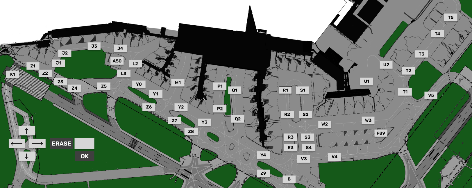
3.2 APRON PUSHBACK MAP
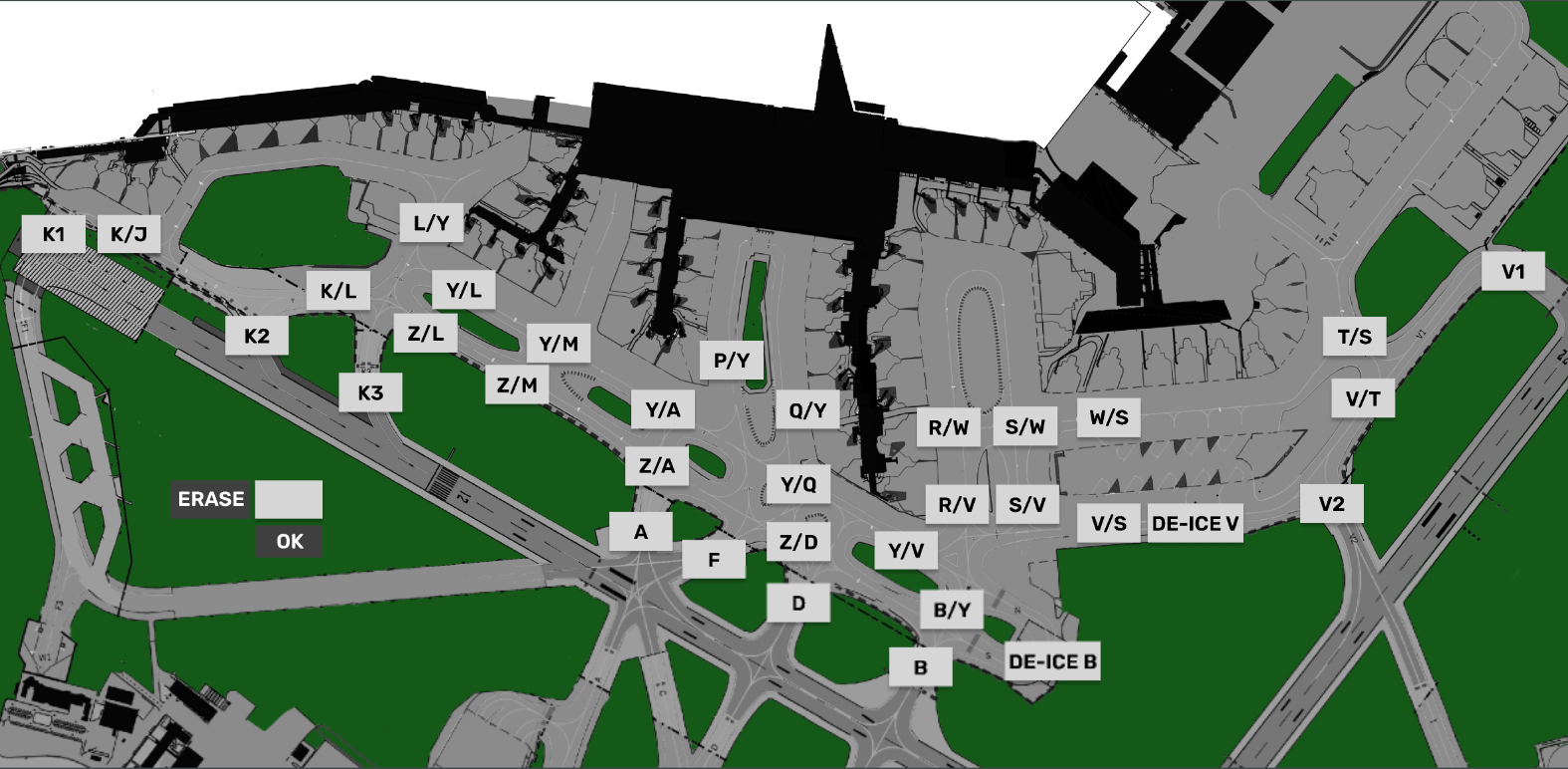
3.3 APRON TAXI MAP
GW+GE- Operation
Containing Description, Operational Procedures and Submenus of the scope called GW+GE............
1.1 Overview
- Scope name: GW+GE,
- Used by: EKCH_GW_TWR, EKCH_GE_TWR
[PIC]
GW+GE scope is used by Ground West and Ground east only, and contains all relevant tasks for perfroming both inbound and outbound responsibilities on the maneuvering area, as well as top-down coverage when Apron is offline.
Even if both GW and GE is online, the scope stays the same.
1.2 Scope Design
Column 1 (ARR INFO) | Column 2 | Column 3 (START/DE-ICE) | Column 4 (DEL) | |
FINAL | PUSHBACK | STARTUP | PLANNED DEP | |
TWY DEP | ||||
RWY ARR | DE-ICE A | |||
TWY ARR | MESSAGES | |||
RWY DEP | ||||
AIRBORNE | STAND |
MESSAGES, FINAL and RWY ARR will not be expanded upon. Refer to chapter 2 for details on MESSAGES.
1.3 PLANNED DEP
Column 4 and the bays associated (OTHERS, SAS, NORWEGIAN) represents planned departures, for use in case there is no delivery or sequence planner is online, resulting in an apron controller providing the clearance.
The three planned departure bays work in an identical fashion as all other scope. Refer to Chapter 3 - CLR DEL for detailed information on its operation.
1.4 STARTUP
The bay STARTUP is for aircraft who has received the ATC Clearance, and has reported ready for startup.
Only the appropriate aprons are represented, meaning if GND is online, no planes from Apron North are visible.
Strip must be moved out of the STARTUP bay and into the PUSHBACK bay when a pushback instruction has been issued.
Strip design
Identical to STARTUP strip for AA+AD. Refer to Chapter 5 - AA+AD for expansion
| |||
ID | Name | Description | Bay |
1 | SI Field | Click to Accept Transfer Click to Initiate Transfer |
|
2 | Callsign | Click to mark or open callsign menu.
| |
3 | Type / WTC | Click either to open "FPL MENU"
| |
4 | STAND | Click to open pushback map to assign release point. | |
5 | TSAT | Click to update TOBT to current time. Color coding as per | |
6 | CTOT | Informational only. Color coding as per Chapter 8 - CDM Operation | |
7 | DEPRWY | Runway of Departure. Click to change. | |
1.5 PUSHBACK
The bay PUSHBACKis for aircraft who has received pushback instruction.
Strip design
Identical to PUSHBACK strip for AA+AD. Refer to Chapter 5 - AA+AD for expansion
1.6 TWY DEP
The bay TWY DEP is the version that TWR see. The main difference from the apron version is that the strips has a larger amount of actions fields, allowing change of headings and altitudes.
Strip design
- SI Field: Click to Initiate Transfer .
- Callsign: Click to Mark.
- STAND Informational only
- DE-ICE: Infromational that De-Ice is required. Color coding as per Chapter 9 - Specific Features
- HS: Hold Short points (Clearance Limit)
- HP: Holding Point assigned
- DEPRWY: Runway of Departure. Click to change.
1.7 TWY ARR
The bay TWY ARR contains the inbound aircraft currently taxiing on a taxiway. The bay contains all strips, including the ones owned by TE/TW and APRON ARR.
Aircraft remains in TWY ARR bay until on stand. If aircraft is inbound to Apron East, West or South GW+GE must manually place the strip in the STAND bay.
Strip design
- SI Field: Click to Accept Transfer
- Callsign: Click to Mark or open callsign menu.
- Type / WTC: Click either to open "FPL MENU"
- ARRRWY: Informational only
- HS: Hold Short points (Clearance Limit)
- STAND Informational only
- TBD
1.8 STAND
The bay STAND contains the inbound aircraft which is on stand, and has been moved there MANUALLY by a controller.
Aircraft remains in STAND bay for 3 minutes after which the strip is removed from exsistence. the 3 minute delay allows controller to move aircraft back in case of inadvertant movement to STAND bay.
Strip design
- ALL Informational
2.1 Startup and Pushback
Startup and Pushback are done in identical fashion to apron and will not be discussed here.
2.2 TWY DEP & Transfer.
Strip is usually handed over from APRON DEP to GW+GE. The strip should be cleared to a holding point, either by:
- Clicking HP and select the appropriate holding point, or
- Clicking HS and select one of the taxiways that is a holding point.
When aircraft approaches the holding point, transfer to appropriate controller in accordance with LAI
2.2.1 Coordination Feature
As GW you should set a sequence and transfer to appropriate holdings points for the sequence. This includes assigning holding points to flights with CTOT, which may have to wait.
TW+TE (Next Controller) May choose to coordinate a different holding point than you have assigned, by the use of the incoming coordination feature.
This is recognized by the HP area of your strip becoming yellow. To accept the coordination:
- Click on HP, and select the same holding point as TE+TW requested you to use.
The yellow background will then disappear and the coordination is complete.
You must move strips in correct order so bottom one is transfered first, to communicate correct sequence.
2.3 Inbound Taxi
Inbound aircraft are transfered to you in accordance with LAI.
2.3.1 General
The HS field of the arrival strip will show you the default taxiway routing towards apron. You do not need to select this again, if you follow this standard routing.
Transfer strip to appropriate apron as per LAI.
2.3.1 Transfer
Transfer is initiated via the SI Field to the appropriate Apron controller. In case the wrong identifier is shown, usage of the quick transfer buttons in the top part of the bay can be used to change the default next controller on the strip.

2.2.2 Apron East/South
For flights destined for Apron East (Cargo/MIL) or South (GA), usage of the "Crossing Strip" is needed to solidify coordiantion for crossing 04R/22L with TE.
Once crossing has been completed, GW+GE, must assume if needed the crossing strip, and remove it.
2.2.1 Coordination Feature
As GW you should use standard taxi routings to apron unless otherwise coordinated.
APRON ARR (Next Controller) May choose to coordinate a different feeder route than you have assigned, by the use of the incoming coordination feature.
This is recognized by the HS area of your strip becoming yellow. To accept the coordination:
- Click on HP, and select the same HS instruction as APRON ARR requested you to use.
The yellow background will then disappear and the coordination is complete.
You must move strips in correct order so bottom one is transfered first, to communicate correct sequence.
3.1 ARR
The ATC Clearance dialogue is divided into three sectors. Departure section, Arrival Section and general information.
3.2 CROSSING
The ATC Clearance dialogue is divided into three sectors. Departure section, Arrival Section and general information.
3.3 LAND/START
The ATC Clearance dialogue is divided into three sectors. Departure section, Arrival Section and general information.
3.4 MEM AID
The ATC Clearance dialogue is divided into three sectors. Departure section, Arrival Section and general information.
3.4 NEW
Open up an empty flightplan to create a new strip. Cannot be an already existing callsign!
3.4 PLANNED
Type in the callsign of an existing aircraft, to find the flightplan and put it in the CLR DEL bay. (planned departures).
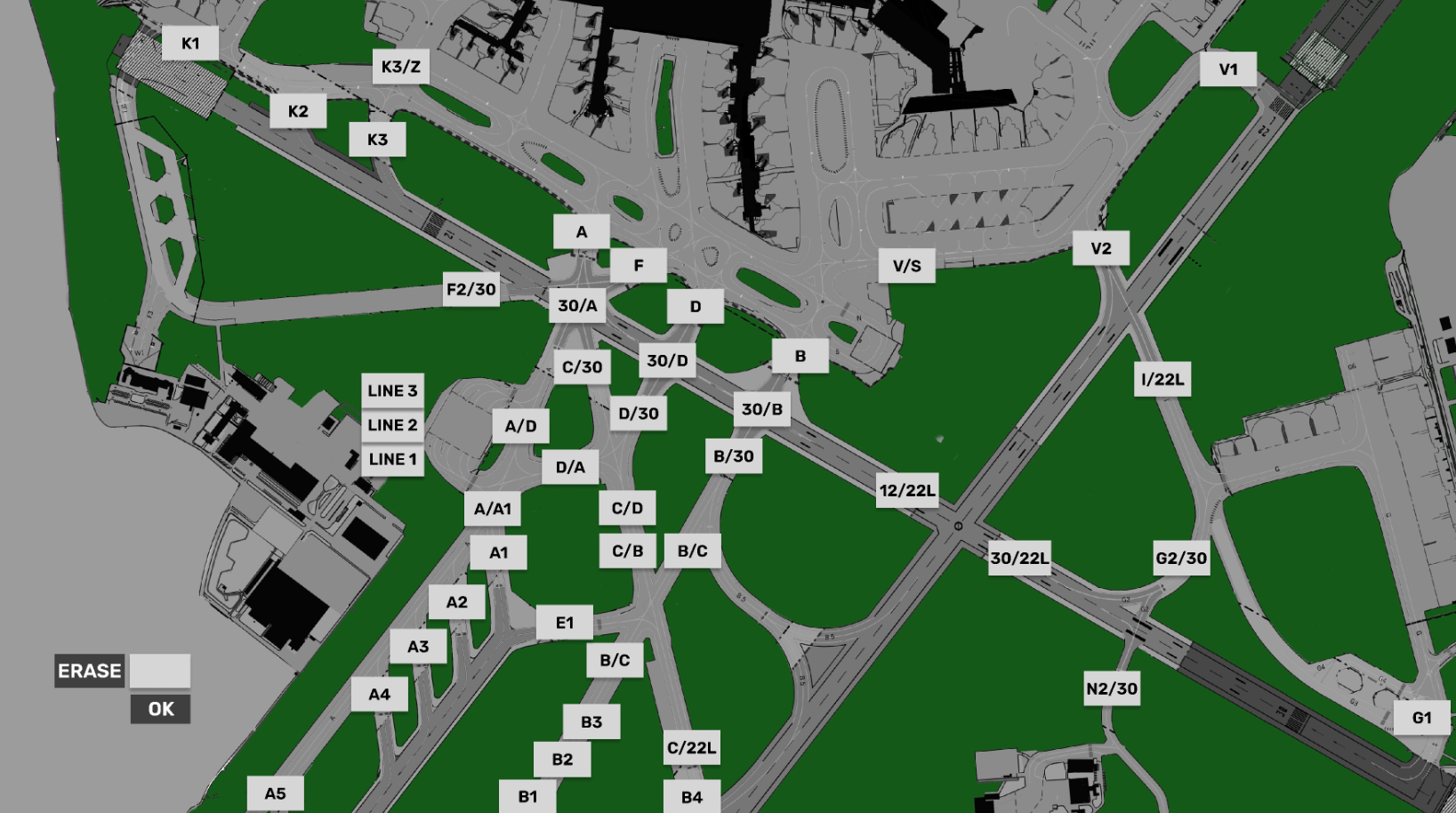
3.5 TWR HS-TAXI CHART
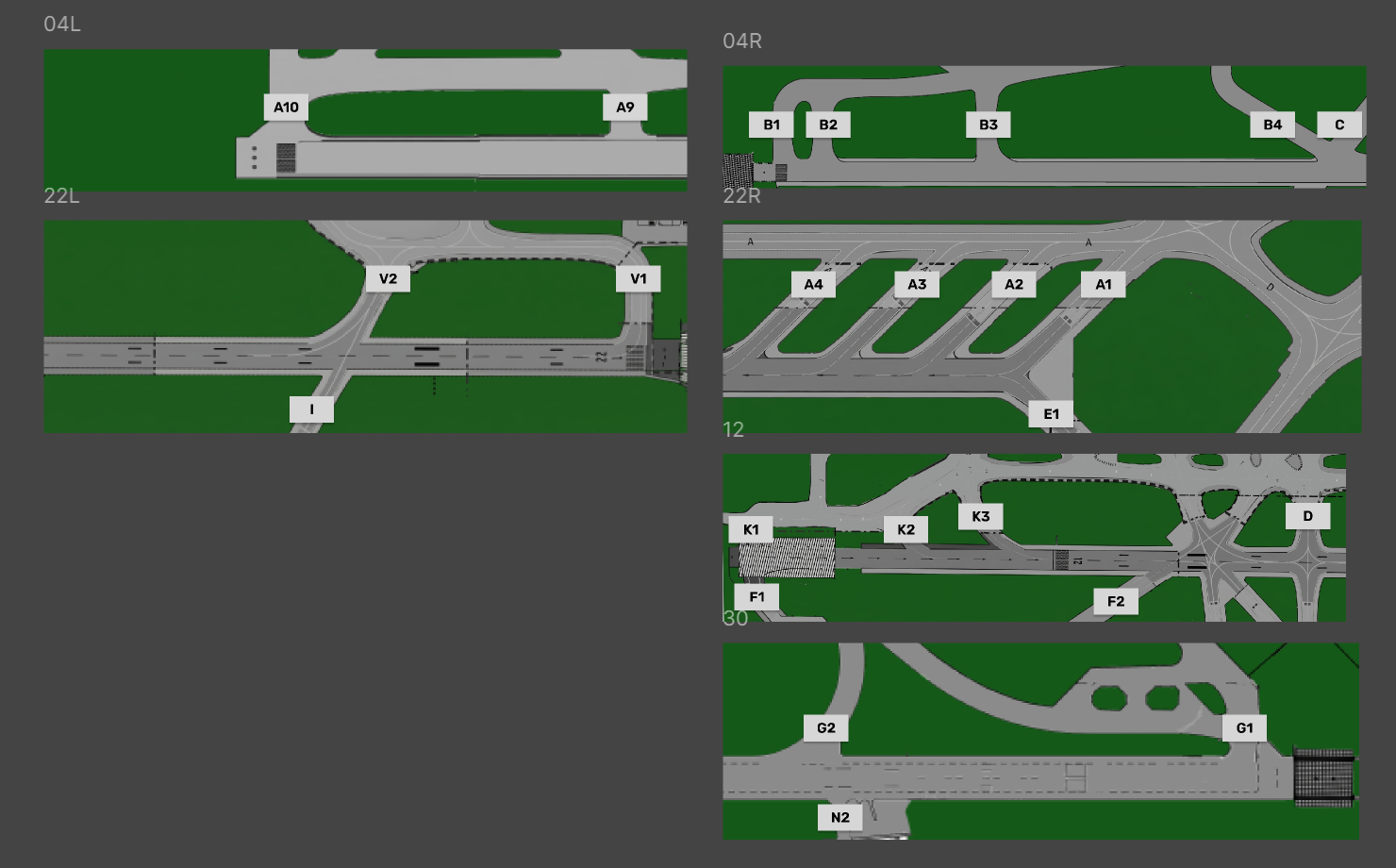
3.6 Holding Point CHART
TE+TW - Operation
Specific Features
CDM Operation
CDM Procedures, What it is? How it works? How to use it? How it is intergrated into FlightStrips...

CDM - Explained
CDM (Collaborative Decision Making) is a complex but vital part of ensuring we can cope with the traffic levels on VATSIM. In order to use CDM properly it is important that you understand
- The logic behind CDM operation
- How to effectively use CDM operation
1.1 Purpose
The first thing you need to understand is that there are TWO (2) different kinds of CDM, They are intertwined and both must be respected.
- A-CDM (Airport - Collaborative Decision Making)
- vIFF CDM (Intergrated Flight and Flow - Collaborative Decision Making)
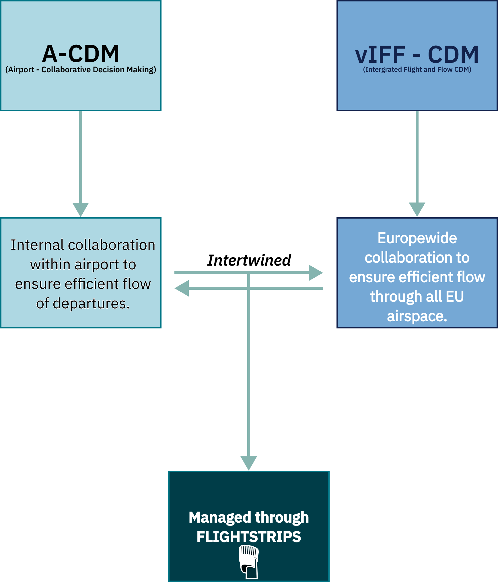
These two systems work towards seperate goals, but must constantly talk to eachother as they are co-dependent.
A change to one of the entities can affect the other one. In order to ensure compliance we have intergrated it all in a user friendly managed manner within FlightStrips
1.2 Abbriviations & Explanations
Many foreign abbreviations are being used for CDM, and we need to cut it into the bone of knowing just the basics for your daily routing:
NOTE: Blue background items are operational items, gray background items are purely adminstrative and not gouvering when controlling
TERM | NAME | DESCRIPTION | USAGE |
EOBT | Estimated Off Block Time | The time the pilot has filed his flightplan to be ready for Startup | Used as initial planning for the TOBT until system, ATC or Pilot says otherwise. |
TOBT | Target Off Block Time | Time the pilot targets to be ready for Startup, depending on the loading process and pax delays | Accepted via pilot EOBT. Can be modified by ATC, the Pilot, CTOTs or automatically by the system at any time. |
TSAT | Target Start Approval Time | Time the ATC targets to provide pilot with his startup, based on capacity restrictions at his TOBT | Based on the filed TOBT, system will calculate the closest time to the TOBT that startup can be approved to respect all flow restrictions |
CTOT | Calculated Take-Off Time | Time pilot must be “Takeoff” in order to respect a restriction en-route or at arrival field | If a vIFF restriction en-route forces aircraft to be airborne in a certain time window a CTOT will be produced to ensure this. |
ASAT | Actual Start Approval Time | Actual time of Start. | Locks the timings in vIFF |
EXOT | Estimated Taxi-Out Time | Expected time between Start and Takeoff | Standard timings based on gate |
TTOT | Target Take-Off Time | Expected Takeoff Time based on Taxi out time and TOBT. | Used to ensure an even departure rate |
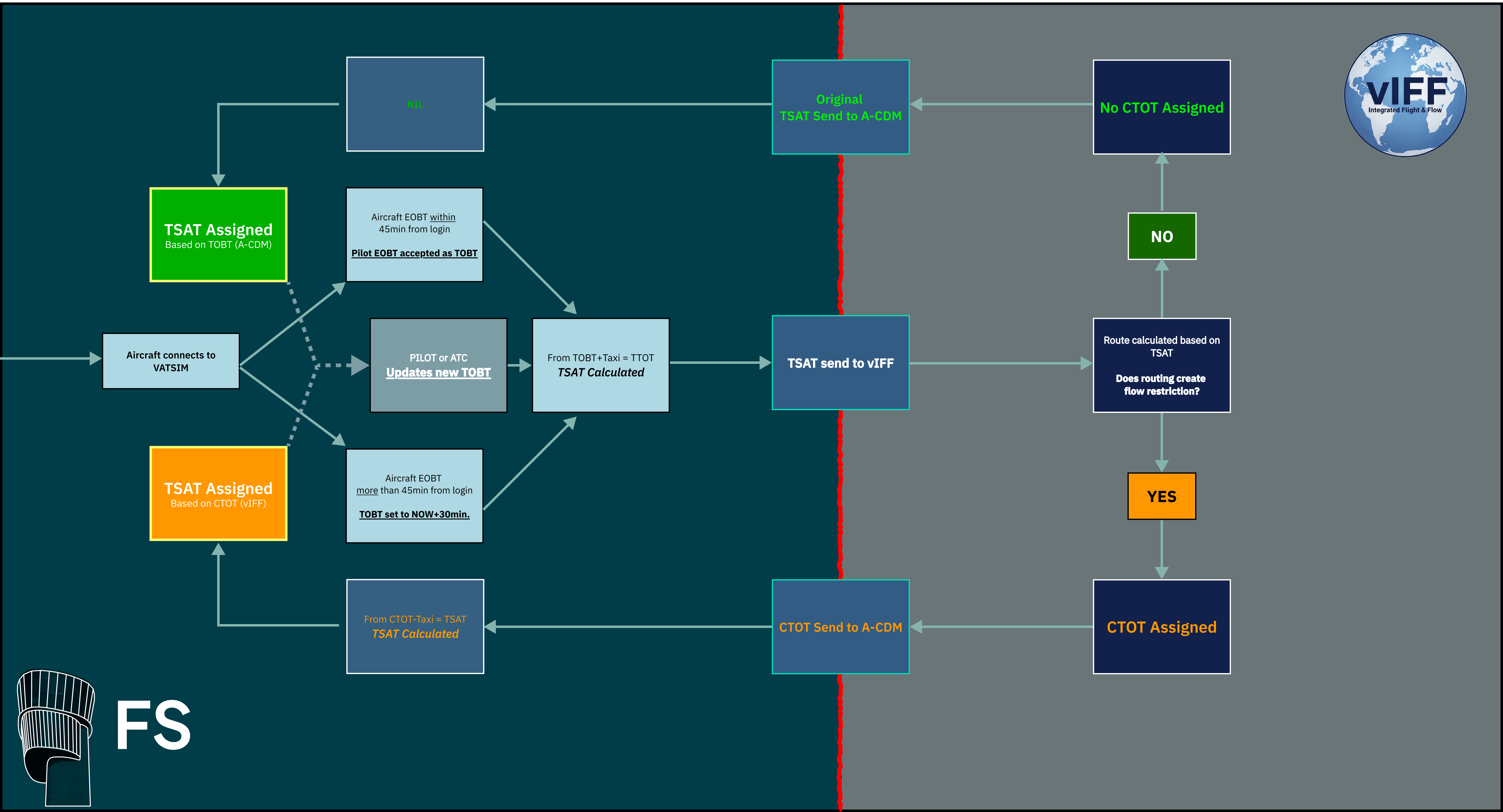
1.3 Flow Control Logic
Flow Control logic works through constant calculations. It is important that you understand the logic.
- Pilot Logs onto VATSIM Network. In his Flightplan he has filed an EOBT.
- FS evaluates the validity of EOBT, and assigns a TOBT.
- A-CDM process begind. Based of the TOBT and available space in sequence a TSAT is "calculated"
- The TSAT is send to vIFF servers for calculation.
- vIFF servers used TSAT to calculate the routing to the destination, and if it exceeds ATC capacity anywhere
- One of two things happen:
- a) No restrictions are identified, and TSAT is returned without edits to A-CDM.
- b) Restrictions identified, CTOT produced to comply with restricionts and returned to A-CDM.
- A-CDM either confirms the TSAT, or calculates a new TSAT based on CTOT restriction
- TSAT is "Assigned" to an aircraft.
- If a TOBT is updated by either pilot or ATC, steps 3-8 are repeated.
Refer to flowchart below for visual explanation
1.4 Calculation
1.4.1 A-CDM
A-CDM needs to calculate a takeoff sequence. The core purpose is to only have as many departures an hour as the airport can handle, and nicely spread out. Therefore it is all based on TTOT (Target Takeoff Time).
- In EKCH the capacity is 40flts/hr and therefore we have 40TTOT spots, spaced 1.5 minutes apart.
The calculation of A-CDM is as follows:
- EOBT is recorded from flightplan, and based on that a TOBT is assigned.
- Stand is recorded and based on RWY in use, a EXOT is established. TOBT+EXOT = TTOT
- Example: TOBT: 1435z. EXOT 12min; 1435z+00:12min = TTOT=1447z
- The system then compares the TTOT to available TTOTs and does one of two things:
- TTOT available: TSAT issued at TOBT
- Example: TTOT: 1447z available, EXOT 12min. 1447z-00:12min = TSAT=1435z
- TTOT occupied: Find next available TTOT, calculate back EXOT, which becomes TSAT
- Example: TTOT: 1453z first available, exit 12min. 1453z-00:12min = TSAT=1441z
- TTOT available: TSAT issued at TOBT
- TSAT assigned to optimize traffic flow depending on what TTOT is available.
1.4.1 vIFF - CDM
vIFF does NOT care about our internal capacity. Only about:
- Enroute Sector capacity
- Arrival TMA capacity
- Arrival Airport capacity
- ECFMP special restrictions
vIFF knows the EXOT of EKCH.
- TSAT which was determined by A-CDM is send to vIFF.
- vIFF, uses TSAT+EXOT to determine TTOT, and afterwards a 3D routing through all airspaces
- If a sector capacity does not allow the flight it will assign a CTOT at a time the capacity allows.
- CTOT is send back to A-CDM
- A-CDM produces a TSAT to fit that CTOT, overriding all other A-CDM restrictions, and delaying subsequent aircrafts TTOT.

 There are two different kinds of layout of CDM. They are similar in colorcoding but differently build up.
- SEQ PLN, AA+AD (or APRON DEP), GND + TWR
- Controlled using conventional FlightStrips techniques
- EST Scope
- Controlled using EST Scope technique.

2.1 CDM Design on Strips
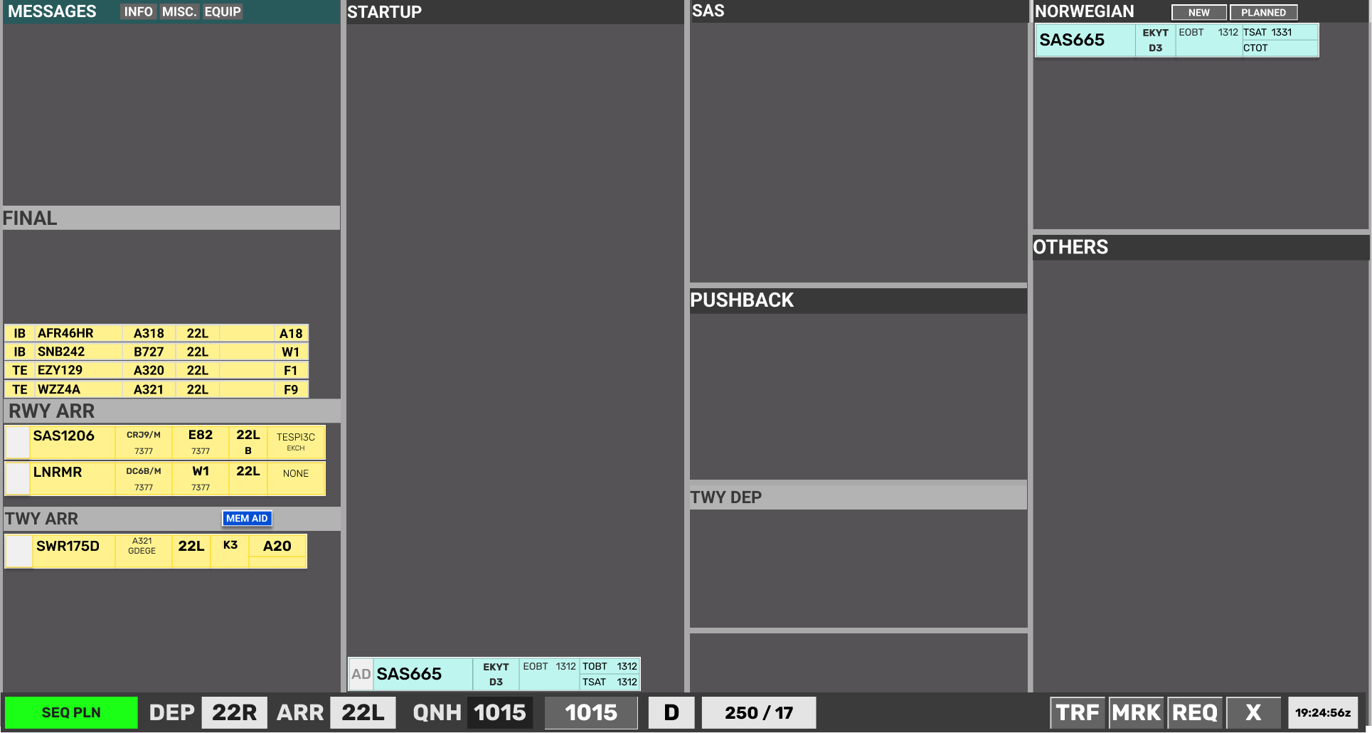
CDM operation IS NOT possible from the CLR DEL scope. CLR DEL must use the SEQ PLN scope.
CDM operation is accomplished via the STARTUP bay in conventional FlightStrips scopes. Aircrafts are sorted with earliest TSAT in bottom.
CDM Design on Strips
2.1.1 Unrestricted Strips
An unrestricted aircraft will not have any color codes until its start-up window.

2.1.2 Startup Approved Strips
An aircraft which has reached its startup window will show a green TSAT. Start-up may be approved.

TSAT Sequence
Start-up window may include a CTOT, but TSAT will still indicate green.

When a TSAT is one (1) minute from expiring, TSAT will indicate Yellow.

When TSAT is expired, TSAT coloring will disappear and a Red TOBT appears.

New TOBT must be filed
2.1.3 A-CDM Delayed Strips
An aircraft which has been delayed by A-CDM due to RWY capacity, will show an Orange TOBT indicating a >5min delay between the TOBT and TSAT.

- When within startup window TSAT will turn green
2.1.4 vIFF Delayed Strips
An aircraft which has been delayed by VIFF due to EU capacity, will show an Yellow CTOT to warn controllers. The CTOT may or may not also be accompanied by an Orange TOBT if the CTOT results in a >5min delay from TOBT

- When within startup window TSAT will turn green

2.2 CDM Design on EST
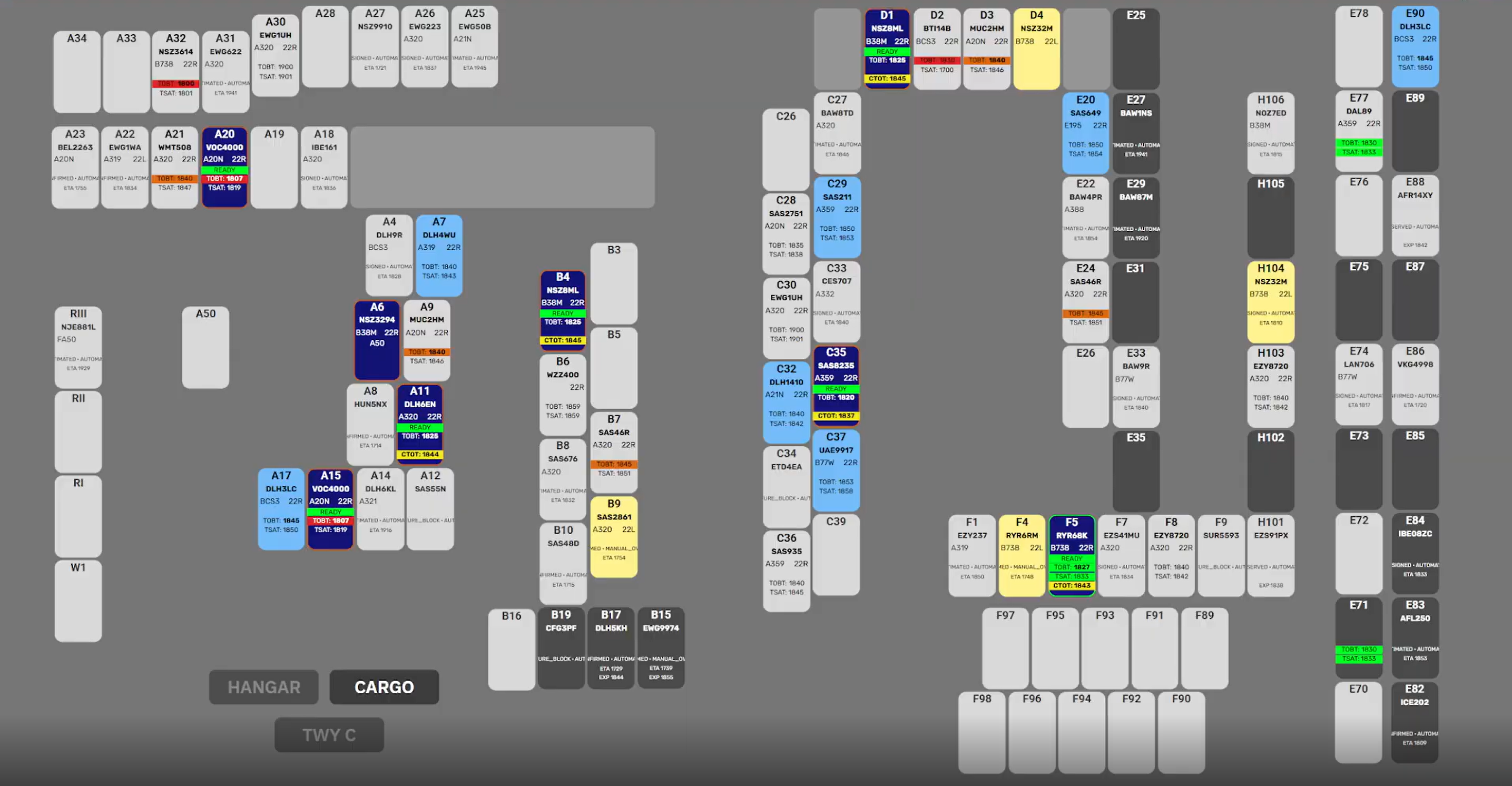
EST Scope has a different layout as it is an image of all the stands. It will show for each individual stand the same color codes as the regular scopes.
CDM Design on EST
2.1.1 Unrestricted Strips
An unrestricted aircraft will not have any color codes until its start-up window.
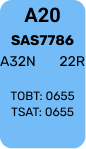
2.1.1 Startup Approved Strips
An aircraft which has reached its startup window will show a green TSAT & TOBT. Start-up may be approved.
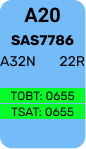
Start-up window may include a CTOT, but TSAT will still indicate green.
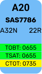
When a TSAT is one (1) minute from expiring, TSAT will indicate Yellow.
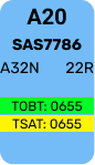
When TSAT is expired, TSAT coloring will disappear and a Red TOBT appears.
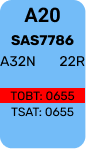
New TOBT must be filed
2.1.1 A-CDM Delayed Strips
An aircraft which has been delayed by A-CDM due to RWY capacity, will show an Orange TOBT indicating a >5min delay between the TOBT and TSAT.
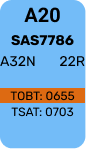
- When within startup window TSAT will turn green
2.1.1 vIFF Delayed Strips
An aircraft which has been delayed by VIFF due to EU capacity, will show an Yellow CTOT to warn controllers. The CTOT may or may not also be accompanied by an Orange TOBT if the CTOT results in a >5min delay from TOBT.
A CTOT which has had an improvement will show in Dark Blue to alert controller of an improvement
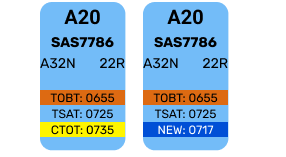
- When within startup window TSAT will turn green


This chapter is about what procedures you must adhere to when managing CDM. You have learned the philosphy and how it looks, now you need to know how to use it. Its developed into 4 subchapters:
- Timings
- EST procedures
- SEQ PLN procedures
- AA+AD procedures
3.1 Acceptable Timing
CDM procedures varies from Apron (and DEL) and Towers.
- GND/DEL prime concern is to ensure Aircraft starts in accordance with TSAT
- TWR prime concern is to ensure Aircraft takes off in accordnace with CTOT
By following the guidelines of Chapter 3 - FlightStrips CDM operation, controller shall adhere to following timings:
- GND/DEL: Start-up approval within -5 min until +5min of TSAT.
- TWR: Takeoff commenced within -5min until +10min of CTOT
Outside of TSAT+6 a new TOBT must be requested
Outside of CTOT+11 TWR should consider severity of exceedance, and allow aircraft to depart only if deemed safe and responsibly to do so by judgement of controller.

3.2 EST Scope Procedures
On EST Screen, clicking on an aircraft on a stand, the menu appears with several different options
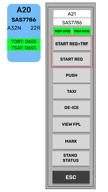
- START REQ + TRF
- START REQ
Which one you need is dependent on the situation of the aircraft. The visual action is similar, but what goes on behind the scenes are different.
START REQ + TRF
START REQ + TRF
Only available when aircraft is WITHIN TSAT Window. It performs following actions
- Approves the aircraft for startup by assigning ASAT, locking the CDM.
- Transfers the strip automatically over to APRON
- Changes appearance to a dark blue color labelled READY above. TOBT & TSAT removed.

START REQ
START REQ
Available if aircraft reports ready before the TSAT window. It performs following actions:
- Selects TOBT to current time in order to look for an earlier TSAT.
- Changes appearance to dark blue color labelled READY above.
- Orange outline, until within TSAT window, then changing to green outline.
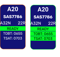
START REQ can be used for:
- TSAT not yet within window. looking for an earlier TSAT
- TSAT expired. Resetting TOBT to find new TSAT
- RDY MSG send by pilot. Will look for an earlier CTOT.
If a START REQ results in a new TSAT found within the window, START REQ + TRF must subsequently be pushed.
START REQ will not look for a new TSAT if current TSAT is within 10min AND has a CTOT attached to it.
OTHER BUTTONS
Other Buttons
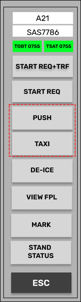
Two additional buttons called PUSH and TAXI is also available. This does the same as START REQ+TRF, but instead of transfering it automatically moves them directly to PUSHBACK and TWY DEP bay respectively.
Useful for when using EST screen, while sitting on a GND or TWR position.

3.3 SEQ PLN Procedures
On SEQ PLN scope, on the strip there are only one click spot you can use.

Clicking on TOBT field, will do the same as START REQ does on the EST scope. It will set TOBT to current time and allow an earlier TSAT to be found. Can be used for:
- TSAT not yet within window. looking for an earlier TSAT
- TSAT expired. Resetting TOBT to find new TSAT
- RDY MSG send by pilot. Will look for an earlier CTOT.
If an earlier TSAT is found, TSAT and TOBT will light up green and start-up can be approved.

Transfer must be done by clicking on the SI Field indicator to commence transfer.
Transfer via SI field will NOT work outside of TSAT window. Manual transfer only in case of CDM malfunction
TSAT click spot will not look for a new TSAT if current TSAT is within 10min AND has a CTOT attached to it.

3.4 AA+AD / GND+TWR Procedures
On AA+AD (And GND+TWR), Strips have a different layout and only displays TSAT and CTOT

NOTE: In above example CTOT is also present
Clicking on TSAT field, will set TOBT to current time and look for a new TSAT. Can be used for:
- TSAT not yet within window. looking for an earlier TSAT
- TSAT expired. Resetting TOBT to find new TSAT
- RDY MSG send by pilot. Will look for an earlier CTOT.
If an earlier TSAT is found, TSAT will light up green and start-up can be approved.

NOTE: In above example CTOT is improved and shows in Blue.
Aircraft can then be transfered into PUSHBACK bay by standard procedures.
If aircraft is positioned in PUSHBACK or TWY DEP bay before TSAT window, the TOBT will automatically be set to current time, and earliest TSAT assigned.
Failure of system to find an earlier TSAT will result in a "Validation status", warning controller.
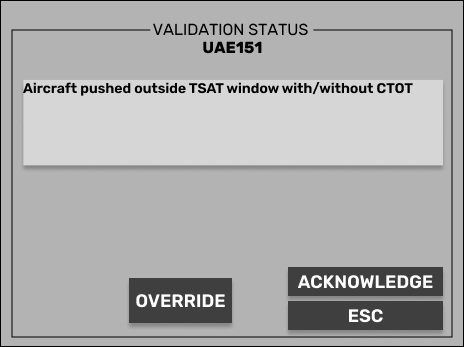
Controller must delay pushback/taxi/takeoff or override to serve delay at holding point