VFR in Finland

Weather minima
The minimum weather conditions where an aircraft can fly under Visual Flight Rules is described in the table below.
| Airspace class | Minimum visibility | Minimum cloud ceiling |
|---|---|---|
| D (Control Zone) | 5 km | BKN or OVC 1000 ft |
| For Special VFR, the minima may be reduced to: | ||
| D (Control Zone) | 1500 m | BKN or OVC 600 ft |
- All Control Zones in Finland are
Dairspace - Check ilmailusaa.fi for weather information
Pilots may also fly in IMC conditions. It is recommended to add RMK/SIMULATED VMC to the flight plan.
Charts
-
eAIP Finland
- From the left menu, navigate to
AD 2for controlled aerodromes - VAC charts are the most useful ones for VFR flying
- From the left menu, navigate to
-
lentopaikat.fi
- Information about uncontrolled aerodromes
-
flyk.com or Fintraffic Sky
- Interactive maps with airspace and weather information
-
Local TRA Charts
- Local Training Areas around airports (in CTR and TMA)
Charts provide the pilots essential information for the flight such as:
- Traffic circuit direction and altitude
- Visual Reporting Points
- Airspace structure, vertical limits, holding areas
- landmarks for visual navigation
- Apron locations, ground layout
Flight Plan
Origin and Destination
Use the ICAO four-letter code e.g. EFOU in the departure and destination fields. If the aerodrome does not have a code, use ZZZZ and specify the aerodrome location in the REMARK field e.g. DEP/KORVATUNTURI or DEST/601542N0193819E.
Route Field
The entries below can be used in the Flight Plan Route field
| ROUTE Field | Explanation |
|---|---|
| OULU CTR | Flight staying within the Control Zone |
| LOIMAA FORSSA | Aerodrome or destination location in plain language |
| TC | Traffic Circuit. You may specify the type and amount of landings in the REMARK field, e.g. RMK/2TGL 1SL 1FS |
Training Area. If you request a certain area, you may insert the name to the REMARK field e.g. RMK/TRAJY04. Check V-LARA Airspace Reservation if you wish to reserve an airspace block. |
|
| LINTU | Visual Reporting Points used when entering or exiting the Control Zone. Pilots should plan the flights via the VRP's as they are establihsed for noise abatement. |
Remarks Field
The following entries can be used in the Flight Plan Remarks field (RMK/...)
| RMK/ | Explanation |
|---|---|
| FS | Full Stop Landing |
| LA | Low Approach |
| TGL | Touch and Go Landing |
| SL | Spot Landing |
| PFL | Practiced Forced Landing |
| PFLR | Practiced Forced Landing back to Runway |
| VFR ON TOP | For a VFR flight to be operated on top of clouds |
| DEP EFOU | Activating VFR flight plan shall be done by radio to the ATS unit whose area of responsibility the aerodrome is located |
| ARR EFTP | Closing VFR flight plan shall be done by radio to the ATS unit whose area of responsibility the aerodrome is located |
| DEP EFIN | Flight plan activation or closure is intended to be given to the EFIN ACC by radio |
| DEP ARR EFRO | Flight plan activation and closure is intended to Rovaniemi ATS by radio |
| FPL CLOSING KUKSA EFRO | Flight plan closing at the boundary of controlled airspace |
Local Traffic Circuit
Local Traffic Circuit is a standardised flight path in the immediate vicinity of an aerodrome used mainly by General Aviation VFR flights.
Every controlled aerodrome has its own Visual Approach Chart (VAC) which includes essential information for flights in the Control Zone. Before your flight, you need to have a general understanding of the traffic circuit legs illustrated below:
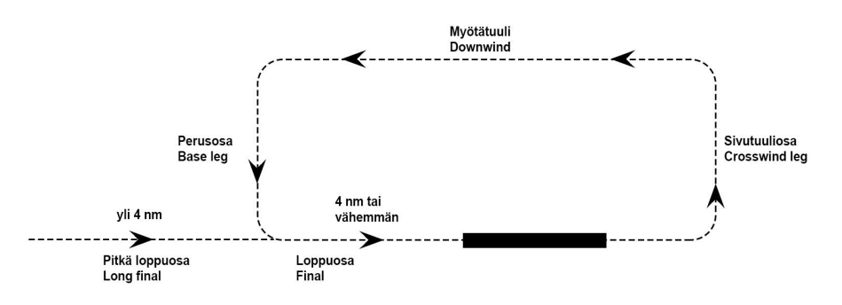
Always use left turns unless otherwise instructed by ATC.
Pilots shall always report when established on the downwind leg, e.g. O-ME, DOWNWIND RUNWAY 30, TOUCH AND GO... If no clearance has been received, pilots shall also report when established on the final leg.
Flight Plan Example
...
Phraseology Example
...
Leaving from Control Zone
Flight Plan Example
...
Phraseology Example
...
Entering to Control Zone
Flight Plan Example
...
Phraseology Example
...
Flights to TMA
Flight Plan Example
...
Phraseology Example
...