Norway Offshore Guide
Introduction
General
Cruising Altitudes
Civil helicopters operating to and from off-shore installations in the North Sea where air traffic services are provided by Norway, will outside controlled airspace be operating at following altitudes, based on area/forecast QNH minimum.
| Magnetic track | Altitude |
|---|---|
| 000 ̊ - 179 ̊ | 3000FT |
| 180 ̊ - 359 ̊ | 2000FT |
If conditions or other circumstances necessitate operations below 2000 FT, ATS shall be informed as soon as possible.
Normally the following altitudes based on radar altimeter will be used.
| Magnetic track | Altitude |
|---|---|
| 000 ̊ - 179 ̊ | 1000FT |
| 180 ̊ - 359 ̊ | 500FT |
Helicopter Routes
Helicopter Routes (HR) are established in that part of the North Sea and Norwegian Sea where Norway is responsible for providing ATS (REF AIP Norway GEN 3.3).
A HR is an ATS-route frequently used by civil helicopters, along which control and flight information service may be provided. They can be directional or bi-directional.
Civil helicopters are normally operating within 4 NM either side of the HR from 1000 FT AMSL to FL 80.
The HR (KY tracks) shall be utilizied outside surveillance coverage. Within surveillance-coverage, flights may be routed on direct track by ATS.
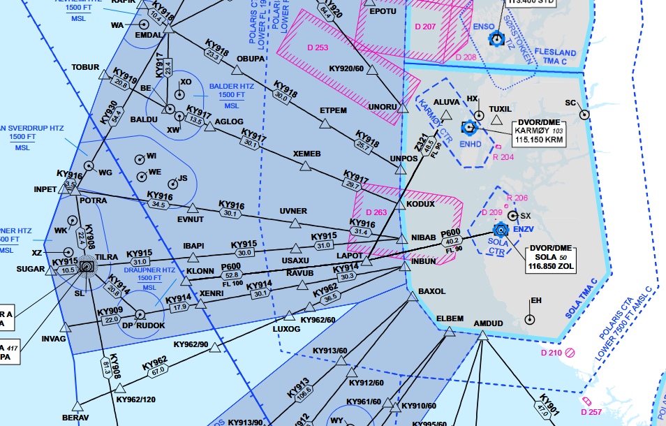
Cruising below a CTA
Flights planned at 1000 FT shall follow a HR. If the flight is planning to follow a bidirectional HR (e.g KY916), this procedure shall be used:
| Magnetic track | Altitude |
|---|---|
| 360 ̊ - 179 ̊ | 1000FT |
| 180 ̊ - 359 ̊ | 2000FT or above* |
Altimeter setting
Within Polaris FIR south of 66.20 ̊N, altimeter setting at 7000 FT or lower is based on actual area QNH.
- ATS will provide QNH for the QNH Areas.
- A change to a new QNH shall be carried out when instructed by ATS.
- Transition Level for a CTA will be determined based on the lowest observed area QNH inside the CTA.
- Transiton Altitude is 7000FT
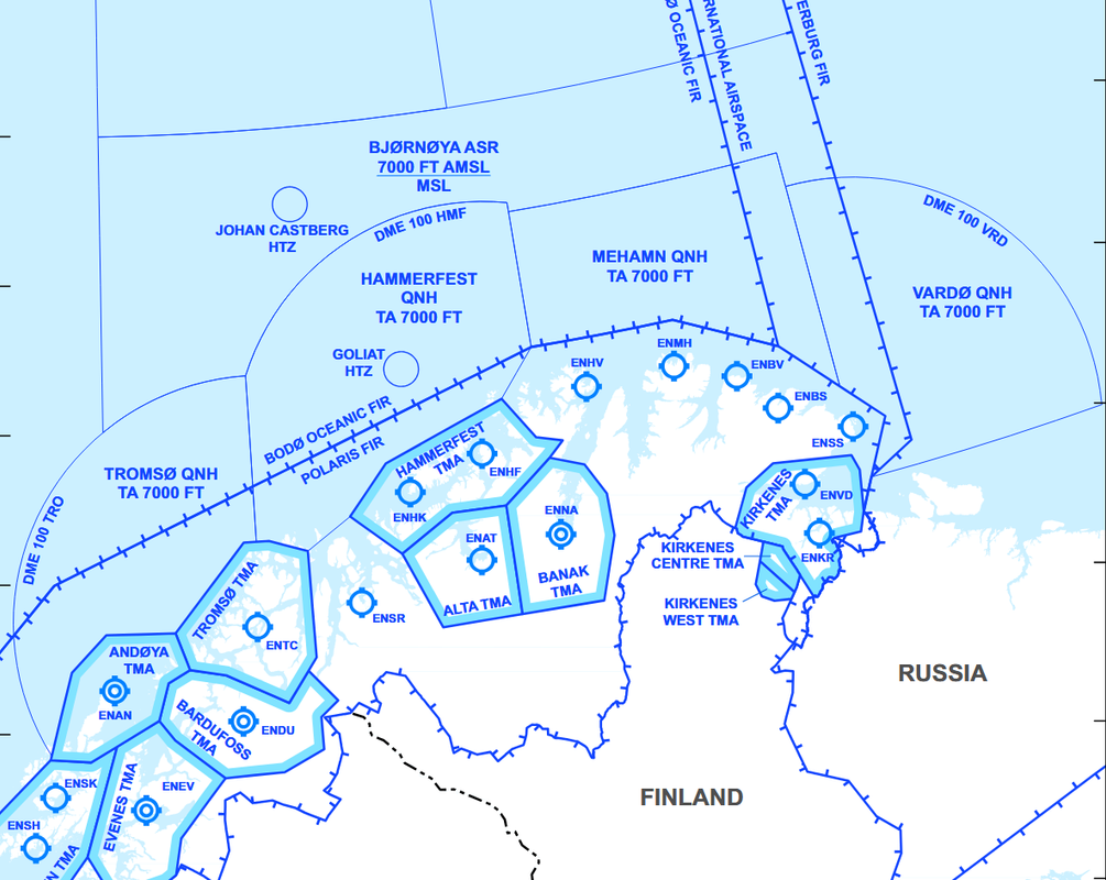
Within Polaris FIR north of 66.20 ̊N, altimeter setting is based on Forecasted Minimum QNH within Altimeter Setting Regions (ASR) Bjørnøya and Tromsøflaket.
- An estimate of the lowest QNH value for a longer period will be made for the Altimeter Setting Region and is available from ATS provider or MET office.
ADS areas
ADS areas are defined areas of Class G airspace, either below a CTA (MSL – 1500 FT), or a specific area (MSL – FL 085) between the main land bases and the main oilfields where radar- and/or ADS-based ATS is provided to ADS equipped helicopters.
Helicopter procedures
Onshore
Instrument Procedures
VFR Procedures
Offshore
Enroute let-down
Standard Offshore Approach
Airborne Radar Approach (ARA)
Communication
Air Traffic Service
Air traffic service provided for helicopter operations on the Norwegian continental shelf:
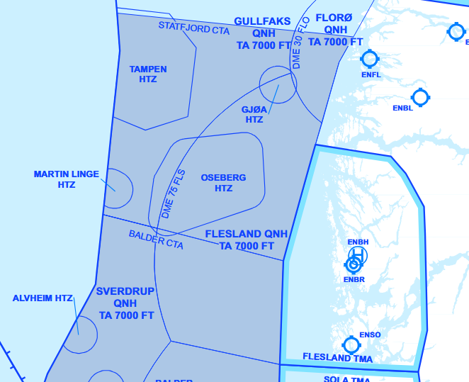
Southern Norway
| Area | Service | Provided by |
|---|---|---|
| Statfjord CTA | Air Traffic Control | Polaris ACC Stavanger |
| Balder CTA | ||
| Ekofisk CTA | ||
| Statfjord ADS | Flight Information | |
| Balder ADS | ||
| Balder ADS | ||
| Tampen HTZ | Tampen HFIS | |
| Ekofisk HTZ | Ekofisk HFIS | |
| HTZ | Polaris ACC Stavanger |
Middle and Northern Norway
| Area | Service | Provided by |
|---|---|---|
| Heidrun CTA | Air Traffic Control | Polaris ACC Bodø |
| Heidrun ADS | Flight Information | |
| Norne ADS | ||
| Barents Sea | ||
| HTZ |
Radio communication
On-deck report
After landing on an installation, pilots shall deliver an on-deck report to the appropriate ATS unit, and shall contain:
- Callsign
- Name on the installation
- Actual time of arrival (ATA)
- Additional information if required (e.g. refueling, shut down)
NOR123, on deck, Gullfaks C, 50
NOR123, on deck, Gullfaks C, 1450, shut down.
Pre-lift-off report
Prior to lift-off from any installation, pilots shall deliver a pre-lift-off report to the appropriate ATS unit, and shall contain:
- Callsign
- Location
- Intended route
- Intended altitude or level
The appropriate ATS unit shall provide traffic information before lift-off is initiated.
NOR123, ready for lift, Gullfaks C, to Flesland via flight planned route, 3000ft.
NOR123, ready for lift, Gullfaks C to Martin Linge via NEBAV direct NASET, 2000ft.
Airborne report
If not covered by other procedures, after take-off from an offshore installation, pilots shall deliver an airborne report to the appropriate ATS unit as soon as practicable, and shall contain:
- Callsign
- Actual time of departure (ATD) from installation
- Actual/intended altitude or level
- If routing via HR and no surveillance service is provided: ETO next reporting point and entry point TMA/TIZ.
NOR123, airborne Gullfaks C at 55, passing 600, climbing 1500.
NOR123, airborne Ekofisk L at 31, passing 700, climbing 1000, estimate AGUVI at 36, ELBEM at 1820.
Operations within a HFIS HTZ
Standard calls while operating within a HFIS HTZ:
- Pre-lift-off report
- Airborne report
- On deck report
During marginal weather conditions, additional information to the standard calls above shall be made when applicable:
- Departure heading and altitude
- Intentions
- ARA
ARA
If planning an Airborne Radar Approach, pilots shall inform the appropriate ATS unit of the following information:
- ARA to (destination)
- Final inbound course
- Course in case of Missed Approach
- Will call passing IP
NOR123, intentions to do an A R A to Ula, inbound course 040, missed approach left turn on course 355, will call passing I P.
Enroute and approach to an oil field
Outbound traffic from landbase to offshore destination, shall give an estimate for an entry point (HTZ) or destination rig on the initial call to ACC.
On initial contact for flights inbound to an oilfield, the initial call or position report shall contain:
- Callsign
- ATIS Information letter (if available)
- Position
- Altitude
- Estimate time over (ETO) point of entry
- Intentions: Visual approach direct to (destination) / Cloud break, direct to (destination) / ARA
- ETA destination
Polaris control, NOR123, with Gullfaks information A, inbound NECUD, 2000ft, estimate NECUD at 40, intentions to do a visual approach direct to Kvitebjørn.
Shuttle (inter-rig flights)
For shuttle flights between adjacent rigs, the Pre-lift-off report and Airborne report are combined into a simplified Liftoff report that shall contain:
- Callsign
- Departure installation
- Destination
- POB
When landed, pilots shall report on deck and omit the time.
NOR123, lifting, Troll C to Troll B, 5 POB.
NOR123, on deck, Troll B.