GW+GE- Operation
Containing Description, Operational Procedures and Submenus of the scope called GW+GE............

1.1 Overview
- Scope name: GW+GE,
- Used by: EKCH_GW_TWR, EKCH_GE_TWR
[PIC]
GW+GE scope is used by Ground West and Ground east only, and contains all relevant tasks for perfroming both inbound and outbound responsibilities on the maneuvering area, as well as top-down coverage when Apron is offline.
Even if both GW and GE is online, the scope stays the same.

1.2 Scope Design
Column 1 (ARR INFO) | Column 2 | Column 3 (START/DE-ICE) | Column 4 (DEL) | |
FINAL | PUSHBACK | STARTUP | PLANNED DEP | |
TWY DEP | ||||
RWY ARR | DE-ICE A | |||
TWY ARR | MESSAGES | |||
RWY DEP | ||||
AIRBORNE | STAND |
MESSAGES, FINAL and RWY ARR will not be expanded upon. Refer to chapter 2 for details on MESSAGES.

1.3 PLANNED DEP
Column 4 and the bays associated (OTHERS, SAS, NORWEGIAN) represents planned departures, for use in case there is no delivery or sequence planner is online, resulting in an apron controller providing the clearance.
The three planned departure bays work in an identical fashion as all other scope. Refer to Chapter 3 - CLR DEL for detailed information on its operation. 
1.4 STARTUP
The bay STARTUP is for aircraft who has received the ATC Clearance, and has reported ready for startup.
Only the appropriate aprons are represented, meaning if GND is online, no planes from Apron North are visible.
Strip must be moved out of the STARTUP bay and into the PUSHBACK bay when a pushback instruction has been issued.
Strip design
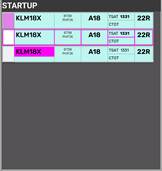
Identical to STARTUP strip for AA+AD. Refer to Chapter 5 - AA+AD for expansion
| |||
ID | Name | Description | Bay |
1 | SI Field | Click to Accept Transfer Click to Initiate Transfer |
|
2 | Callsign | Click to mark or open callsign menu.
| |
3 | Type / WTC | Click either to open "FPL MENU"
| |
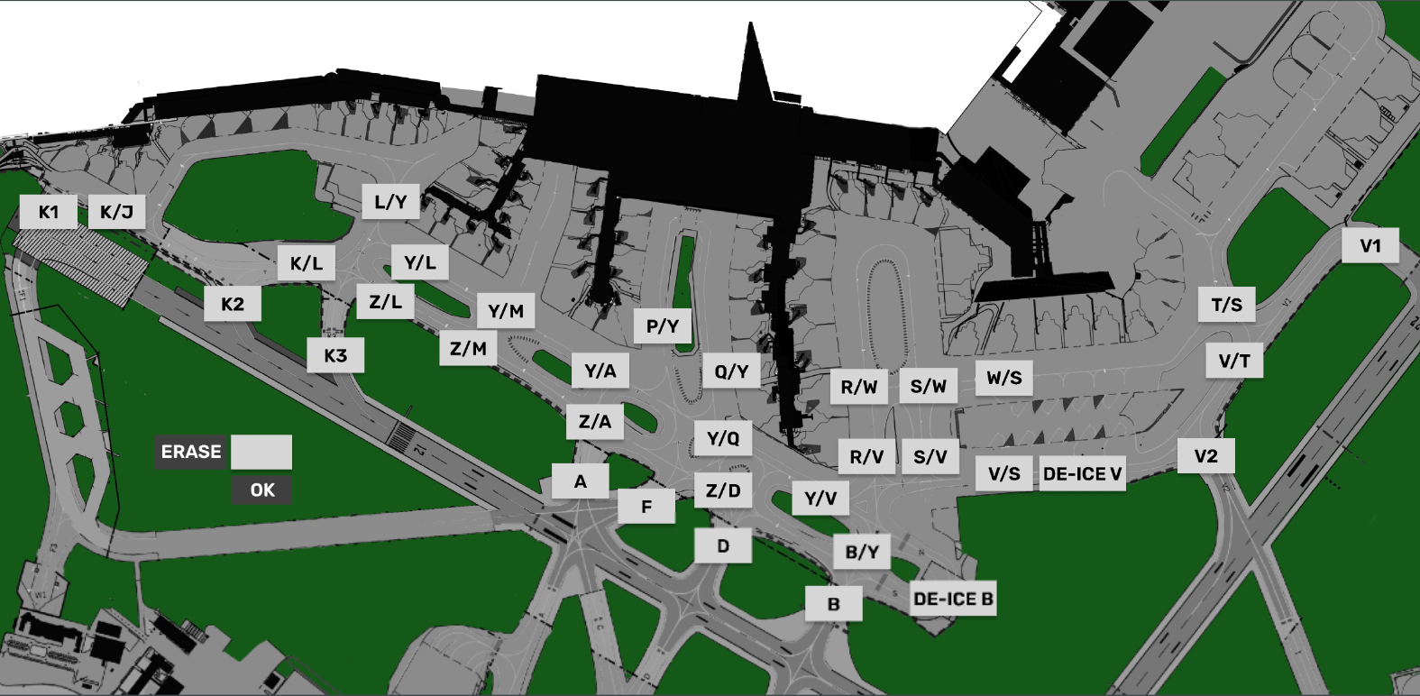
4 | STAND | Click to open pushback map to assign release point. | |
5 | TSAT | Click to update TOBT to current time. Color coding as per | |
6 | CTOT | Informational only. Color coding as per Chapter 8 - CDM Operation | |
7 | DEPRWY | Runway of Departure. Click to change. | |



1.5 PUSHBACK
The bay PUSHBACKis for aircraft who has received pushback instruction.
Strip design
Identical to PUSHBACK strip for AA+AD. Refer to Chapter 5 - AA+AD for expansion
1.6 TWY DEP
The bay TWY DEP is unique in being the only one of its kind with Two Sections
This is important because there is a difference!
- The upper section of TWY DEP, is ONLY visible to APRON, and used for hold short instructions within apron
- The Lower section of TWY DEP, is ALSO visible to all TWR scopes, used for hold short of RWY 12/30.
NOTE: The purpose of this is not to overload TWR with Departure information until it is actually relevant.
Strip design
- SI Field: Click to Initiate Transfer
 .
. - Callsign: Click to Mark.
- STAND Informational only
- DE-ICE: Infromational that De-Ice is required. Color coding as per Chapter 9 - Specific Features
- HS: Hold Short points (Clearance Limit)
- HP: Holding Point assigned
- DEPRWY: Runway of Departure. Click to change.
1.7 TWY ARR
The bay TWY ARR contains the inbound aircraft currently taxiing on a taxiway. The bay contains all strips, including the ones owned by TE/TW and GE/GW.
Aircraft remains in TWY ARR bay until on stand, after which they must be manually moved to the STAND bay.
Strip design
- SI Field: Click to Accept Transfer

- Callsign: Click to Mark or open callsign menu.
- Type / WTC: Click either to open "FPL MENU"
- ARRRWY: Informational only
- HS: Hold Short points (Clearance Limit)
- STAND Informational only
- TBD
1.8 STAND
The bay STAND contains the inbound aircraft which is on stand, and has been moved there MANUALLY by a controller.
Aircraft remains in STAND bay for 3 minutes after which the strip is removed from exsistence. the 3 minute delay allows controller to move aircraft back in case of inadvertant movement to STAND bay.
Strip design
- ALL Informational


2.1 Startup and Pushback
A strip is transfered by SEQPLN (or EKCH_DEL), when startup is approved in accordance with TSAT requirements.
If neither of the above mentioned entities are online, APRON DEP must complete CDM procedures in accordance with Chapter 8.
Click on SI Field when aircraft call up, to confirm transfer, and approve a pushback. This you can do by one of three actions, specified below in order of most preferred:
- Click on STAND to select release point. Aircraft is automatically moved to PUSHBACK bay.
- Click and drag aircraft to PUSHBACK bay. Select release point thereafter within 10 seconds.
- Click and drop aircraft to PUSHBACK bay. Select release point thereafter within 10 seconds.
- Click and drag aircraft to PUSHBACK bay. Select release point thereafter within 10 seconds.
Once Pushback is complete and aircraft reports ready for taxi, you need to continue the process. This you can do by one of the three actions, specified below in order of most prefered:
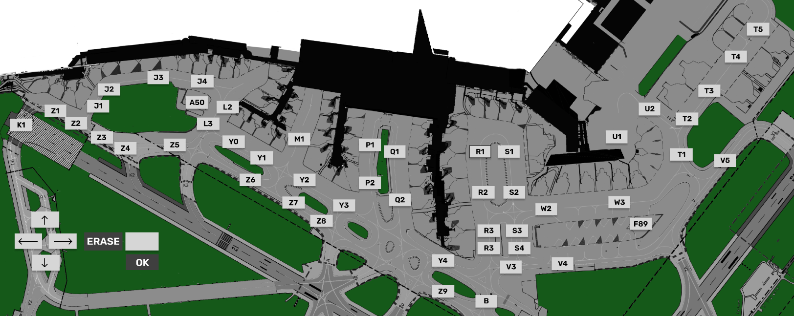
- Click on RELEASE POINT to select taxi clearance limit. Aircraft is automatically moved to TWY DEP bay1.
- Click and drag aircraft to approrpiate TWY DEP bay. Select taxi clearance limit thereafter.
- Click and drop aircraft to approrpiate TWY DEP bay. Select taxi clearance limit thereafter.
- Click and drag aircraft to approrpiate TWY DEP bay. Select taxi clearance limit thereafter.
1Strip is automatically put into Upper Section or Lower Section, depending on the clearance limit selected.

2.2 TWY DEP & Transfer.
Once aircraft goes to TWY DEP, you will see the SI Field being populated with the identifier for next position. The position takes "cross coupling" into account, so it will show GW (Ground West on 118.580) even if he is not online, but one of the tower controllers has crosscoupled the frequency.
Once aircraft approches the clearance limit for transfer click on SI Field to initiate transfer, and ask aircraft to contact next frequency.
If the SI Field for whatever reason does not contain the correct next controller, manually select next frequency by one of two alternative options.
- Click on Aircraft and select TRF to open manual transfer dialogue (explaining in Chapter 2)
- Click on Aircraft and select TW/TE/GW/GE in the small menu above
NOTE: The second option does NOT transfer, but simply changes the unit on the SI field. You must still transfer.
You must ensure that aircraft is in the Lower Section of TWY DEP before transfering!
You must move strips in correct order so bottom one is transfered first, to communicate correct sequence. to GE/GW.

2.3 Inbound Taxi
Inbound aircraft will be transfered to you cleared to the appropriate clearance limit in accordance with LAI. Once in contact, you must accept the strip, by clicing on SI field, and provide further taxi to stand.
It is NOT recommended to change the stand after transfer. The gate assignment system takes many factors into account in assigning stands.
If you really need to change stand clicking on the STAND field in the flightplan allows you to request a new stand. It is highly prefered to automatically request a stand instead of manually selecting it.
Pilots should NOT be allowed to taxi to a prefered stand unless you are aboslutely sure they will disconnect as soon as they arrive and will not return to the stand for another flight. Pilots can request stands via EFB.
Once aircraft approaches the stand, immediately move the strip to STAND bay, to clear up space.


3.1 MEM AID
The ATC Clearance dialogue is divided into three sectors. Departure section, Arrival Section and general information.
3.2 APRON PUSHBACK MAP
3.3 APRON TAXI MAP