GW+GE- Operation
Containing Description, Operational Procedures and Submenus of the scope called GW+GE............

1.1 Overview
- Scope name: GW+GE,
- Used by: EKCH_GW_TWR, EKCH_GE_TWR
[PIC]
GW+GE scope is used by Ground West and Ground east only, and contains all relevant tasks for perfroming both inbound and outbound responsibilities on the maneuvering area, as well as top-down coverage when Apron is offline.
Even if both GW and GE is online, the scope stays the same.

1.2 Scope Design
Column 1 (ARR INFO) | Column 2 | Column 3 (START/DE-ICE) | Column 4 (DEL) | |
FINAL | PUSHBACK | STARTUP | PLANNED DEP | |
TWY DEP | ||||
RWY ARR | DE-ICE A | |||
TWY ARR | MESSAGES | |||
RWY DEP | ||||
AIRBORNE | STAND |
MESSAGES, FINAL and RWY ARR will not be expanded upon. Refer to chapter 2 for details on MESSAGES.

1.3 PLANNED DEP
Column 4 and the bays associated (OTHERS, SAS, NORWEGIAN) represents planned departures, for use in case there is no delivery or sequence planner is online, resulting in an apron controller providing the clearance.
The three planned departure bays work in an identical fashion as all other scope. Refer to Chapter 3 - CLR DEL for detailed information on its operation. 
1.4 STARTUP
The bay STARTUP is for aircraft who has received the ATC Clearance, and has reported ready for startup.
Only the appropriate aprons are represented, meaning if GND is online, no planes from Apron North are visible.
Strip must be moved out of the STARTUP bay and into the PUSHBACK bay when a pushback instruction has been issued.
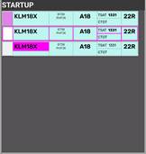
Strip design
Identical to STARTUP strip for AA+AD. Refer to Chapter 5 - AA+AD for expansion
| |||
ID | Name | Description | Bay |
1 | SI Field | Click to Accept Transfer Click to Initiate Transfer |
|
2 | Callsign | Click to mark or open callsign menu.
| |
3 | Type / WTC | Click either to open "FPL MENU"
| |
4 | STAND | Click to open pushback map to assign release point. | |
5 | TSAT | Click to update TOBT to current time. Color coding as per | |
6 | CTOT | Informational only. Color coding as per Chapter 8 - CDM Operation | |
7 | DEPRWY | Runway of Departure. Click to change. | |


1.5 PUSHBACK
The bay PUSHBACKis for aircraft who has received pushback instruction.
Strip design
Identical to PUSHBACK strip for AA+AD. Refer to Chapter 5 - AA+AD for expansion
1.6 TWY DEP
The bay TWY DEP is the version that TWR see. The main difference from the apron version is that the strips has a larger amount of actions fields, allowing change of headings and altitudes.
Strip design
- SI Field: Click to Initiate Transfer
 .
. - Callsign: Click to Mark.
- STAND Informational only
- DE-ICE: Infromational that De-Ice is required. Color coding as per Chapter 9 - Specific Features
- HS: Hold Short points (Clearance Limit)
- HP: Holding Point assigned
- DEPRWY: Runway of Departure. Click to change.
1.7 TWY ARR
The bay TWY ARR contains the inbound aircraft currently taxiing on a taxiway. The bay contains all strips, including the ones owned by TE/TW and APRON ARR.
Aircraft remains in TWY ARR bay until on stand. If aircraft is inbound to Apron East, West or South GW+GE must manually place the strip in the STAND bay.
Strip design
- SI Field: Click to Accept Transfer
- Callsign: Click to Mark or open callsign menu.
- Type / WTC: Click either to open "FPL MENU"
- ARRRWY: Informational only
- HS: Hold Short points (Clearance Limit)
- STAND Informational only
- TBD
1.8 STAND
The bay STAND contains the inbound aircraft which is on stand, and has been moved there MANUALLY by a controller.
Aircraft remains in STAND bay for 3 minutes after which the strip is removed from exsistence. the 3 minute delay allows controller to move aircraft back in case of inadvertant movement to STAND bay.
Strip design
- ALL Informational


2.1 Startup and Pushback
AStartup stripand isPushback transferedare by SEQPLN (or EKCH_DEL), when startup is approveddone in accordanceidentical with TSAT requirements.
If neither of the above mentioned entities are online, APRON DEP must complete CDM procedures in accordance with Chapter 8.
Click on SI Field when aircraft call up,fashion to confirm transfer,apron and approvewill anot pushback.be Thisdiscussed you can do by one of three actions, specified below in order of most preferred:
Click on STAND to select release point. Aircraft isautomaticallymoved to PUSHBACK bay.Click and drag aircraft to PUSHBACK bay. Select release point thereafter within 10 seconds.Click and drop aircraft to PUSHBACK bay. Select release point thereafter within 10 seconds.
Once Pushback is complete and aircraft reports ready for taxi, you need to continue the process. This you can do by one of the three actions, specified below in order of most prefered:
Click on RELEASE POINT to select taxi clearance limit. Aircraft isautomaticallymoved to TWY DEP bay1.Click and drag aircraft to approrpiate TWY DEP bay. Select taxi clearance limit thereafter.Click and drop aircraft to approrpiate TWY DEP bay. Select taxi clearance limit thereafter.
1Strip is automatically put into Upper Section or Lower Section, depending on the clearance limit selected.here.

2.2 TWY DEP & Transfer.
OnceStrip aircraftis goesusually handed over from APRON DEP to TWYGW+GE. DEP,The youstrip willshould seebe cleared to a holding point, either by:
- Clicking HP and select the
SIappropriateFieldholdingbeingpoint,populatedor - Clicking
withHStheandidentifier for next position. The position takes "cross coupling" into account, so it will show GW (Ground West on 118.580) even if he is not online, butselect one of thetowertaxiwayscontrollersthathasiscrosscoupleda holding point.
When aircraft approaches the frequency.holding point, transfer to appropriate controller in accordance with LAI
2.2.1 Coordination Feature
As GW you should set a sequence and transfer to appropriate holdings points for the sequence. This includes assigning holding points to flights with CTOT, which may have to wait.
TW+TE (Next Controller) May choose to coordinate a different holding point than you have assigned, by the use of the incoming coordination feature.
OnceThis aircraftis approchesrecognized by the clearanceHP limitarea forof transferyour clickstrip onbecoming SIyellow. FieldTo to initiate transfer, and ask aircraft to contact next frequency.
Ifaccept the SI Field for whatever reason does not contain the correct next controller, manually select next frequency by one of two alternative options. coordination:
- Click on
AircraftHP, and selectTRFthe same holding point as TE+TW requested you toopen manual transfer dialogue (explaining in Chapter 2)Click on Aircraft and select TW/TE/GW/GE in the small menu above
NOTE: The secondyellow optionbackground doeswill NOTthen transfer,disappear but simply changes the unit onand the SIcoordination field.is You must still transfer.complete.
You must ensure that aircraft is in the Lower Section of TWY DEP before transfering!
You must move strips in correct order so bottom one is transfered first, to communicate correct sequence. to GE/GW.

2.3 Inbound Taxi
Inbound aircraft will beare transfered to you cleared to the appropriate clearance limit in accordance with LAI.
2.3.1 General
The HS field of the arrival strip will show you the default taxiway routing towards apron. You do not need to select this again, if you follow this standard routing.
Transfer strip to appropriate apron as per LAI.
2.3.1 Transfer
Transfer is initiated via the SI Field to the appropriate Apron controller. In case the wrong identifier is shown, usage of the quick transfer buttons in contact,the youtop mustpart acceptof the strip,bay bycan clicingbe on SI field, and provide further taxi to stand.
It is NOT recommendedused to change the standdefault afternext transfer. The gate assignment system takes many factors into account in assigning stands.
If you really need to change stand clickingcontroller on the STANDstrip. field

2.2.2 Apron East/South
For flights destined for Apron East (Cargo/MIL) or South (GA), usage of the flightplan"Crossing allowsStrip" is needed to solidify coordiantion for crossing 04R/22L with TE.
Once crossing has been completed, GW+GE, must assume if needed the crossing strip, and remove it.
2.2.1 Coordination Feature
As GW you should use standard taxi routings to apron unless otherwise coordinated.
APRON ARR (Next Controller) May choose to coordinate a different feeder route than you have assigned, by the use of the incoming coordination feature.
This is recognized by the HS area of your strip becoming yellow. To accept the coordination:
- Click on HP, and select the same HS instruction as APRON ARR requested you to
requestuse.
The newyellow stand.background Itwill then disappear and the coordination is highly prefered to automatically request a stand instead of manually selecting it. complete.
Pilots shouldYou NOTmust bemove allowedstrips in correct order so bottom one is transfered first, to taxicommunicate tocorrect a prefered stand unless you are aboslutely sure they will disconnect as soon as they arrive and will not return to the stand for another flight. Pilots can request stands via EFB.
Once aircraft approaches the stand, immediately move the strip to STAND bay, to clear up space.sequence.


3.1 ARR
The ATC Clearance dialogue is divided into three sectors. Departure section, Arrival Section and general information.
3.2 CROSSING
The ATC Clearance dialogue is divided into three sectors. Departure section, Arrival Section and general information.
3.3 LAND/START
The ATC Clearance dialogue is divided into three sectors. Departure section, Arrival Section and general information.
3.4 MEM AID
The ATC Clearance dialogue is divided into three sectors. Departure section, Arrival Section and general information.
3.24 APRONNEW
Open MAPup an empty flightplan to create a new strip. Cannot be an already existing callsign!
3.4 PLANNED
Type in the callsign of an existing aircraft, to find the flightplan and put it in the CLR DEL bay. (planned departures).
3.5 TWR HS-TAXI CHART
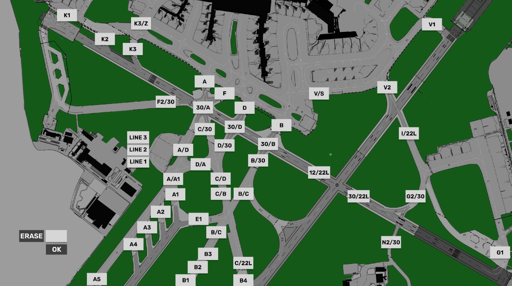
3.36 APRONHolding TAXIPoint MAPCHART